


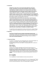
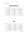


CABLE RUN
(m)
C.S.A. OF EACH
CONDUCTOR (mm)
CABLE
RESISTANCE Ω
% POWER LOSS
INTO 8Ω LOAD
% POWER LOSS
INTO 4Ω LOAD
10
2.5
4.0
6.0
0.14
0.09
0.06
1.7
1.1
0.73
3.5
2.2
1.5
25
2.5
4.0
6.0
0.35
0.22
0.14
4.3
2.7
1.8
8.6
5.4
3.6
50
2.5
4.0
6.0
0.69
0.43
0.29
8.6
5.4
3.6
17.0
11.0
7.2
100
2.5
4.0
6.0
1.38
0.86
0.58
17.0
11.0
7.2
35.0
22.0
14.0
4. Polarity Checking
It is most important to check the polarity of the wiring. A simple method of doing this
without a pulse based polarity checker for LF units is as follows: Connect two wires to
the +ve and -ve terminals of a PP3 battery. Apply the wire which is connected to the
+ve terminal of the battery to the speaker cable leg which you believe to be
connected to the red speaker terminal and likewise the -ve leg of the battery to the
black speaker terminal
If you have wired it correctly the LF drive unit will move forward, indicating the wiring
is correct. All that remains now is to connect the +ve speaker lead to the +ve
terminal on the amplifier and the -ve lead to the -ve terminal on the amplifier. If
however the LF driver moves backwards, the input connections need to be inverted.
If problems are encountered, inspect the cable wiring in the first instance. It should
also be noted that different amplifier manufacturers utilise different pin configurations
and polarity conventions, if you are using amplifiers from more than one
manufacturer, check the polarity at the amplifiers as well as the loudspeakers.
5. Amplification & Power Handling
As with all professional loudspeaker systems, the power handling is a function of
voice coil thermal capacity. Care should be taken to avoid running the amplifier into
clip (clipping is the end result of overdriving any amplifier). Damage to the
loudspeaker will be sustained if the amplifier is driven into clip for any extended
period of time. Headroom of at least 3dB should be allowed. When evaluating an
amplifier, it is important to take into account its behaviour under low impedance load
conditions. A loudspeaker system is highly reactive and with transient signals it can
require more current than the nominal impedance would indicate.
Generally a higher power amplifier running free of distortion will do less damage to
the loudspeaker than a lower power amplifier continually clipping. It is also worth
remembering that a high powered amplifier running at less than 90% of output power
generally sounds a lot better than a lower power amplifier running at 100%. An
amplifier with insufficient drive capability will not allow the full performance of the
loudspeaker to be realised.
It is important when using different manufacturers amplifiers in a single installation
that the have very closely matched gains, the variation should be less than +/- 0.5dB.
This precaution is important to the overall system balance when only a single
compressor/limiter or active crossover is being used with multiple cabinets; it is
therefore recommended that the same amplifiers be used throughout.
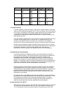
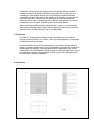
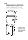
6. Power Selection (i6T AW ICT)
Determine the maximum power in watts needed at each speaker location. The i6 AW
ICT transformer can be tapped at 60w, 30w, 15w, with an extra 7.5W tapping for
70.7V line systems via the rotary switch located on the metal plate at rear of the