SWRA004A
26 TRF1500 Integrated Dual-Band RF Receiver User’s Guide
Low-Band Cascaded Test Guide
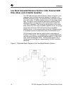
This section involves measuring the cascaded performance of the
Low Band LNA, Low Band MIXER and Low Band IF Amp. An
external SAW filter is utilized to complete the RF receiver section.
All tests apply for an IF output terminated into a 1 k
Ω
differential
load. To match the differential IF output to the 50
Ω
test
equipment a transformer balun is used. All unused ports are
terminated into 50
Ω
.
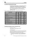
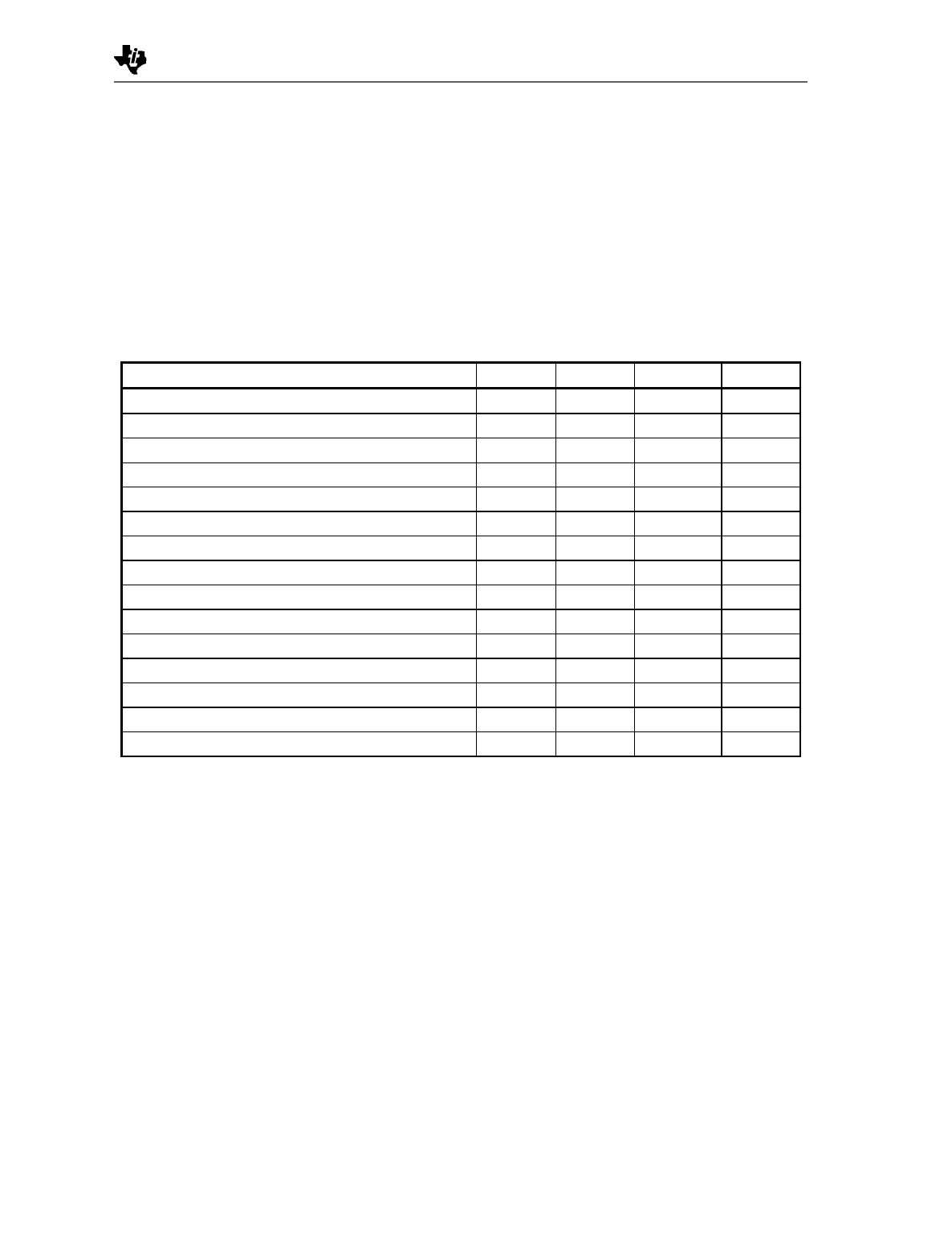
Table 3. LB LNA, LB Mixer, SAW Filter, and LB IF Amp Parameters
PARAMETERS Min Typ Max UNIT
RF Frequency Range 869 881.5 894 MHz
LO Frequency Range 979.52 992.02 1004.52 MHz
IF Frequency 110.52 MHz
RF Input Power -30 dBm
LO Input Power -5 dBm
Power Conversion Gain 26.0 dB
Power Conversion Gain Reduction 19.0 dB
Noise Figure 2.5 dB
RF Input Return Loss 5.6 dB
LO Input Return Loss 16.5 dB
LO Buffer Output Power -10.3 dBm
Power Leakage LO In to RF In -53.0 dBm
Third Order Input Intercept Point (IIP3) -9.7 dBm
1dB RF Input Compression Point -21.0 dBm
1dB Blocking Point -18.0 dBm
LOW-Band Cascaded: Power Conversion Gain
Control state: 011000
SEE APPENDIX A: TEST BENCH SETUPS
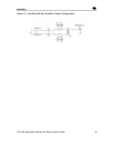
Test setup Figure 20
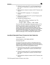
The low band power conversion gain (dB) is the measured power
(dBm) at the IF frequency minus the RF source power (dBm). It is
measured using a RF source and a spectrum analyzer.
1) Set the RF source power (RF P
in
) and the desired frequency
(see Table 3). Connect the RF source to the EVM RF port,
J10.


