SWRA004A
22 TRF1500 Integrated Dual-Band RF Receiver User’s Guide
Low-Band Mixer
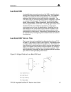
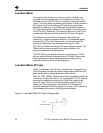
The purpose of the mixer in a down-conversion receiver is to
translate incoming signals from one frequency to another. The
low-band mixer in the TRF1500 is a three port high-side injected
circuit. The mixer takes two known input signals, a radio frequency
(RF) signal and a local oscillator (LO) signal and mixes them
together to create a sum and difference intermediate frequency
(IF). High-side injection means the LO is higher in frequency than
the RF by the IF frequency. The output of the mixer is the IF and
contains the difference and the sum of the RF and LO signals.
The difference of the RF and LO signals is the desired IF
frequency in a down-conversion receiver. The undesired signal,
the sum of the RF and LO frequencies, can be attenuated by
using a low pass filter. The low-band mixer section of the
TRF1500 is a Gilbert cell design with open collector outputs. The
Gilbert cell structure was used for its robust isolation and
harmonic suppression characteristics.
The TRF1500 mixer typically achieves a noise figure of 7.5 dB
with an input third order intercept point of 3.5 dBm. Stand-alone
mixer performance can be ascertained by reconfiguring the
evaluation board as noted on the datasheet.
Low-Band Mixer RF Input
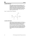
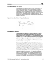
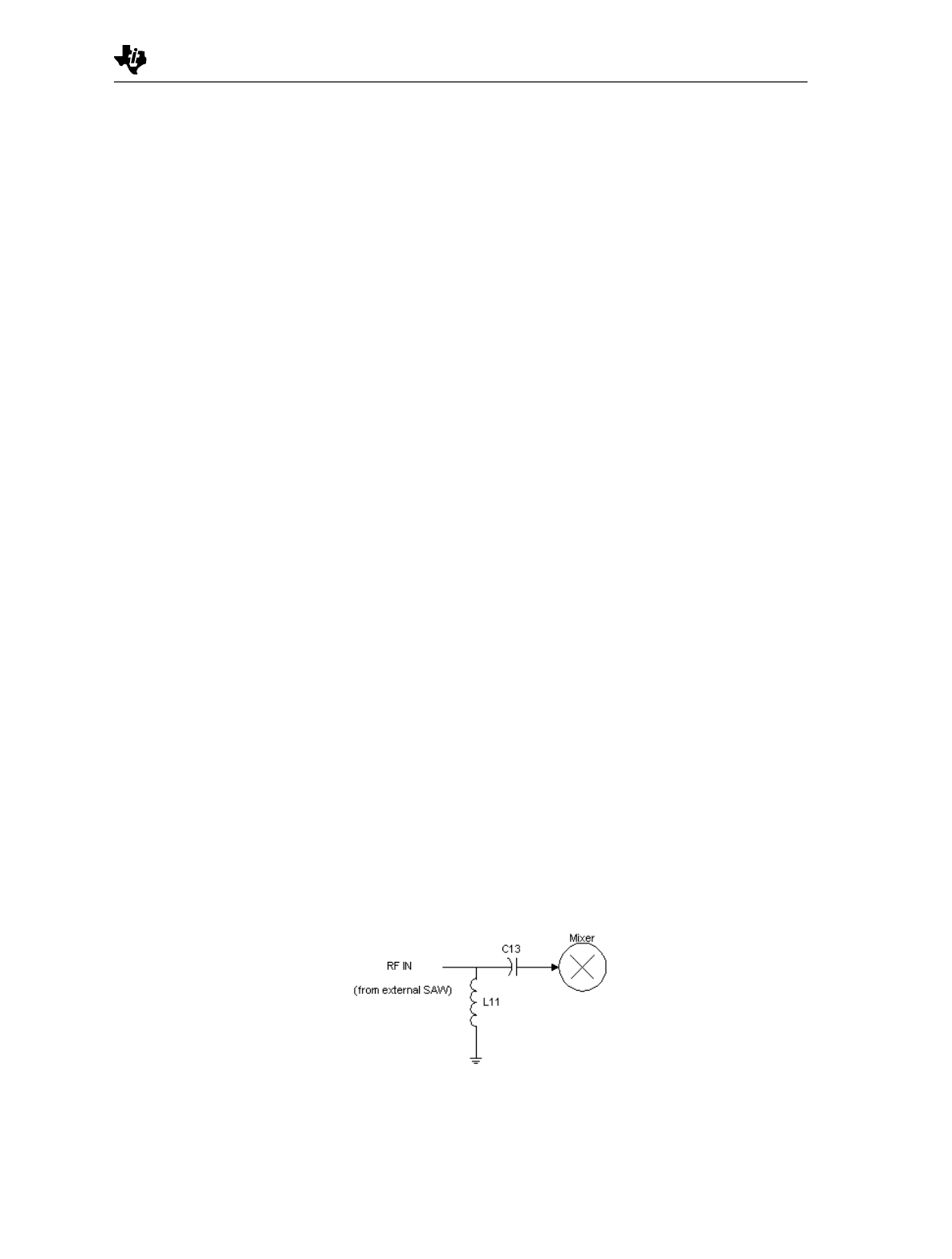
Figure 7 details the mixer RF input configuration. The signal from
the LNA passes through the external image-reject SAW filter and
back into the device’s low-band mixer input terminal
(MIX_IN_LOW_BAND). Minimal mixer input impedance matching
is required. A high-pass shunt-L (L11) and series-C (C13) network
are used for impedance matching the SAW filter output to the
mixer RF input. The shunt inductor presents a short at the IF
frequency. This configuration minimizes the IF leakage and
prevents unwanted interfering signals at, or near, the IF frequency
from degrading the mixer’s noise figure performance.
Figure 7. Low-Band Mixer RF Input Configuration


