


Description
1-4
General Information
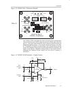
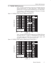
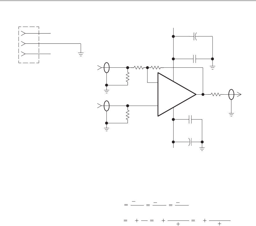
Figure 1–4. THS3001 Rev. A EVM Schematic
–IN
Inverting
+IN
Noninverting
Out
R1
49.9 Ω
R3
49.9 Ω
–V
CC
2
3
4
6
7
+
–
U1
THS3001
J2
J4
+
C2
6.8 µF
J3
R2
1 kΩ
R4
1 kΩ
R5
49.9 Ω
C4
0.1 µF
C1
6.8 µF
+
C3
0.1 µF
V
CC
–V
CC
V
CC
GND
J1
1
–V
CC
2
3
V
CC
Rev. A
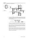
Even though the THS3001 is a current-feedback amplifier, the gain of the EVM
can easily be changed to support a particular application by simply changing
the ratio of resistors R1, R4, and R5 (R1, R2, and R4 for Rev. A) as described
in the following equations:
Inverting Gain
R
F
R
G
R1
R5
R4
R2
(Rev. A)
Noninverting Gain 1
R
F
R
G
1
R1
R4 R5
1
R4
R2 R1
(Rev. A)
In addition, some applications, such as those for video, may require the use
of 75-Ω cable and 75-Ω EVM input termination and output isolation resistors.
Any of the resistors on the EVM board can be replaced with a resistor of a
different value; however, care must be taken because the surface-mount
solder pads on the board are somewhat fragile and will not survive many
desoldering/soldering operations.
Because of the current feedback architecture, extra care must be taken to
ensure that a feedback resistor is always included in the design. In addition,
there must never be a capacitor directly in the feedback path between the
amplifier output and the noninverting input. Disregarding this guideline will
likely result in a part that oscillates.