


www.ti.com
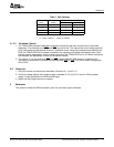
V
DD
= 3.6 V, 10%
0
0.50
1
1.50
2
2.50
4 9 14 19 24 29 34
P
O
− Output Power − W
R
L
− Load Resistance − W
See Note
V
DD
= 5 V, 1%
V
DD
= 2.5 V, 1%
V
DD
= 2.5 V, 10%
V
DD
= 3.6 V, 1%
V
DD
= 3.6 V, 10%
2Operation
2.1QuickStartforStand-AloneOperation
Operation
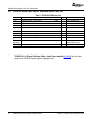
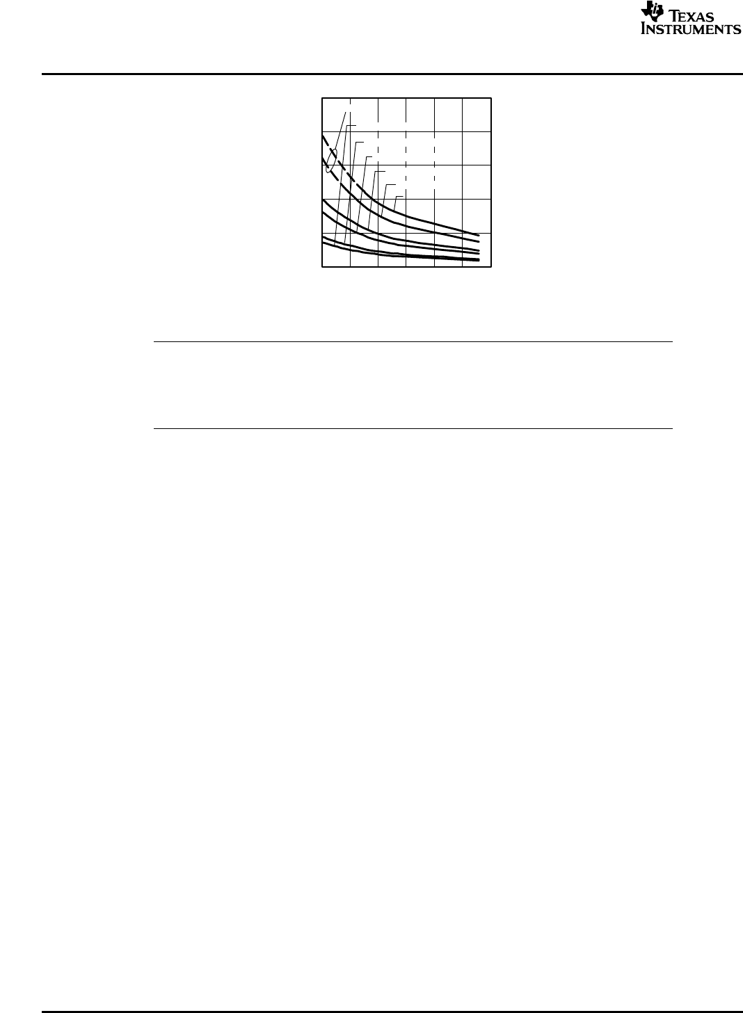
Figure1.TPA2012D2OutputPower
Note:
ThedashedportionofthecurveindicatestheregionwheretheTPA2012D2YZH(WCSP)
isthermallylimited.Outputpowerinthisregionwilldependontheheatdissipation
providedbythecircuitboard.TPA2012D2RTJ(QFN)isnotthermallylimitedandcan
achieveoutputpoweralongboththesolidanddashedportionsofthecurves.
ThissectiondescribeshowtooperatetheTPA2012D2EVM.
UsethefollowingstepswhenoperatingtheTPA2012D2EVMstandaloneorwhenconnectingtheEVM
intoexistingcircuitsorequipment.
2.1.1PowerandGround
1.EnsuretheexternalpowersourcesaresettoOFF.
2.Setthepowersupplyvoltagebetween2.5Vand5.5V.Whenconnectingthepowersupplytothe
EVM,makesuretoattachthegroundconnectiontotheGNDheaderpinfirstandthenconnectthe
positivesupplytotheVDDheaderpin.Verifythattheconnectionsaremadetothecorrectheaderpins.
2.1.2InputsandOutputs
2.1.2.1Audio
1.Ensurethattheaudiosourceissettotheminimumlevel.
2.Connecttheaudiosourcetotheinputs,INL+/-andINR+/-.
–Foradifferentialaudiosource,connecttheaudiosourcedirectltytotheappropriateinputheader
pins.
–Forasingle-endedaudiosource,connecttheaudiosourcetothenegativeinputheaderpinofthe
appropriatechannelandgroundthepositiveaudioinputheaderpin.
3.Connectspeakers(4Ω?32Ω)totheoutputpins,OUTL+/-andOUTR+/-.
2.1.2.2GainControl
1.TheGAIN0andGAIN1jumperscontrolthegainsettingoftheTPA2012D2.Withthejumpersinstalled,
theG0andG1pinsarepulledtoground.SeeTable1forgainsettingvalues.
2SLOU174A–February2005–RevisedApril2005 TPA2012D2AudioPowerAmplifierEvaluationModule