


www.ti.com
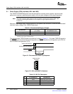
2.1PowerSupply(PSU)Interface(J901andJ900)
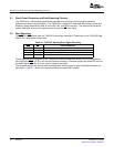
Output-StagePowerSupply
SystemPowerSupply
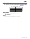
RESET
>1ms
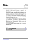
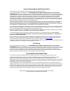
4
1
2
3
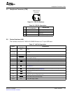
PCBConnector
(TopView)
PowerSupply(PSU)Interface(J901andJ900)
TheTAS5518-5152K8EVMmodulemustbepoweredfromexternalpowersupplies.High-endaudio
performancerequiresastabilizedpowersupply,withlowripplevoltageandlowoutputimpedance.
Note:Thelengthofpower-supplycablemustbeminimized.IncreasingthelengthofPSUcable
isequaltoincreasingthedistortionfortheamplifierathighoutputlevelsandlow
frequencies.
Maximumoutput-stagesupplyvoltagedependsofthespeakerloadresistance.Checktherecommended
maximumsupplyvoltageintheTAS5152datasheet.
Table2-1.RecommendedSupplyVoltages
VOLTAGELIMITATIONSCURRENT
DESCRIPTION
(4-ΩLOAD)RECOMMENDATIONS
Systempowersupply15Vto20V0.3A
Output-stagepowersupply0Vto35V6A
(1)
(1)
Theratedcurrentcorrespondstotwo-channelfullscale(80Weach),whichisadequatefora
standardeight-channelamplifierdesign.
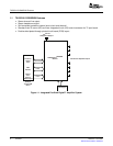
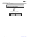
TherecommendedTAS5152power-upsequenceisshowninFigure2-1.ForproperTAS5152operation,
theRESETsignalshouldbekeptlowduringpowerup.RESETispulledlowduringpowerupfor200ms
bytheonboardresetgenerator(U73).
Figure2-1.RecommendedPower-UpSequence
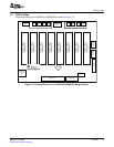
Figure2-2.J901andJ900PinNumbers
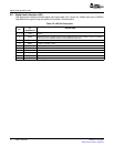
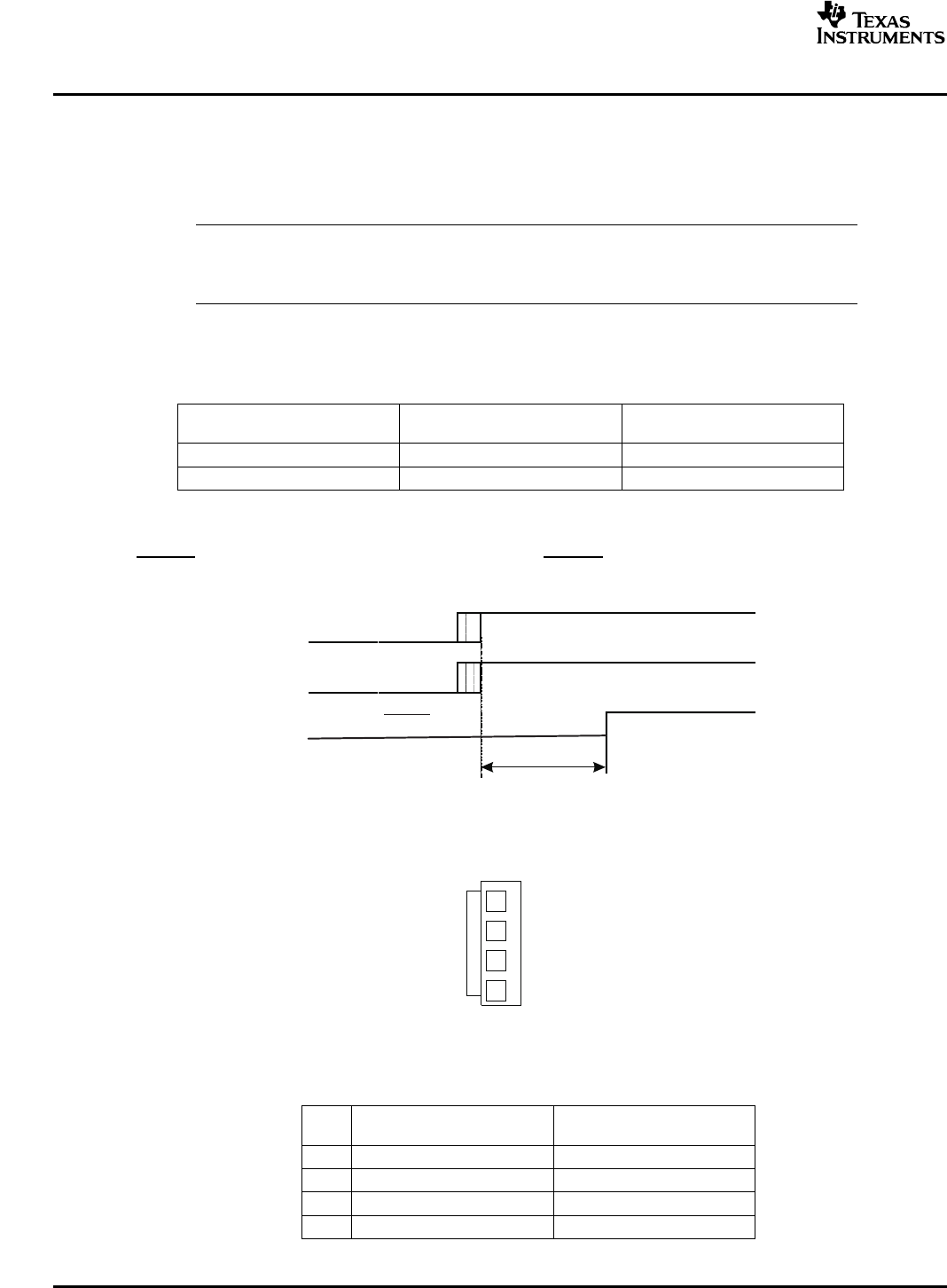
Table2-2.J901PinDescription
PINNETNAME
DESCRIPTION
NO.ATSCHEMATICS
1PVDDOutput-stagepowersupply
2SYSTEMSystempowersupply
3GNDGround
4GNDGround
SystemInterfaces 12SLEU074–June2006
SubmitDocumentationFeedback