


3Quick-SetupGuide
3.1ElectrostaticDischargeWarning
3.2UnpackingtheEVM
3.3PowerSupplySetup
www.ti.com
Quick-SetupGuide
ThissectiondescribestheTAS5102/3EVMboardinregardstopowersuppliesandsysteminterfaces.It
providesinformationregardinghandlingandunpacking,absoluteoperatingconditions,andadescription
ofthefactorydefaultswitchandjumperconfiguration.
Thesectionalsoprovidesastep-by-stepguidetoconfiguringtheTAS5102/3EVMfordeviceevaluation.
ManycomponentsontheTAS5102/3EVMaresusceptibletodamagebyelectrostaticdischarge(ESD).
CustomersareadvisedtoobserveproperESDhandlingprecautionswhenunpackingandhandlingthe
EVM,includingtheuseofagroundedwriststrapatanapprovedESDworkstation.
CAUTION
FailuretoobserveESDhandlingprocedurescanresultindamagetoEVM
components.
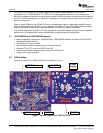
OnopeningtheTAS5086-TAS5102EVMorTAS51033EVMpackage,ensurethatthefollowingitemsare
included:
•1pc.TAS5102/3EVMPowerStageBoard
•1pc.HPL-MC012Modulator/InputBoard
•Becausethissystemhasstandardconnectors,nocablesaresupplied
•1pc.TAS5102/3EVMCD-ROM.
Ifanyoftheseitemsaremissing,contacttheTexasInstrumentsProductInformationCenternearestyou
toinquireaboutareplacement.
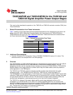
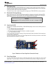
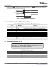
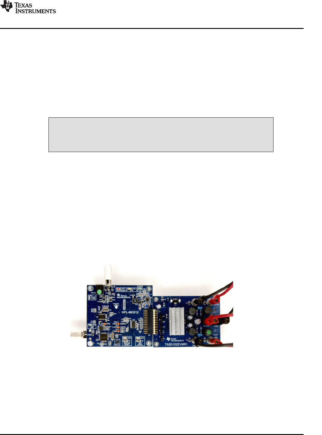
ConnecttheModulator/InputboardtothePowerStageboardwiththedockingconnectorsoneachboard.
Usecarebecausethisconnectorisnotkeyed.
Figure2.ModulatorandPowerStageBoardConnectionExample
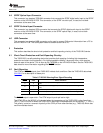
TopoweruptheEVM,onepowersupplyisneededforsystempower,logicandgate-drive,andforoutput
stagesupply.ThepowersupplyisconnectedtotheEVMwithbananacablesorstrippedinsulatedwire.
SLLU106–August2008TAS5102EVMandTAS5103EVMfortheTAS5102andTAS5103DigitalAmplifierPowerOutputStages7
SubmitDocumentationFeedback