


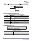
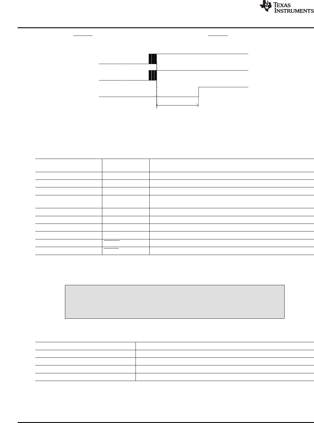
Outputstagepowersupply
RESET
>1ms
Systempowersupply
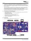
4.2J1AmplifierConnectiontoMC012ControllerModule
4.3LoudspeakerConnectors(J3-J6)
SystemInterfaces
www.ti.com
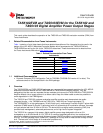
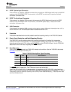
TherecommendedTAS5102/3power-upsequenceisshowninFigure4.ForproperTAS5102/3
operation,theRESETsignalshouldbekeptlowduringpowerup.RESETispulledlowduringpowerup
for200msbytheonboardresetgenerator(U2).
Figure4.RecommendedPower-UpSequence
Table4.J9/J10PinDescriptionAmplifier/ControllerConnector
Net-Nameat
PinNo.Description
Schematics
1,2,5,6,10,11,28DGNDLow-currentgroundformodulator/controller
3,4PVDD1PVDDbufferedthrough24-Ωresistortopowerthemodulator/controller
7OTWOvertemperaturewarningfromtheamplifier(T>125°C)
8,9,13,15,17,19,20,21,
NCNotconnected
22,23,25,27
12PWM_AChannelAPWMsignalfrommodulator
14PWM_BChannelBPWMsignalfrommodulator
16PWM_CChannelCPWMsignalfrommodulator
18PWM_DChannelDPWMsignalfrommodulator
24RESETResetstheTAS5102/3
26FAULTPowerstagefaultindicator
CAUTION
Bothpositiveandnegativespeakeroutputsarefloatingandmaynotbe
connectedtoground(e.g.,throughanoscilloscope).
Table5.OutputPinDescription
Net-NameatSchematicsDescription
OUT_ASpeakerpositiveoutput
OUT_BSpeakernegativeoutput
OUT_CSpeakerpositiveoutput
OUT_DSpeakernegativeoutput
TAS5102EVMandTAS5103EVMfortheTAS5102andTAS5103DigitalAmplifierPowerOutputStages 10SLLU106–August2008
SubmitDocumentationFeedback