


2.5ADCInterface
2.6BoardPowerupGeneralGuidelines
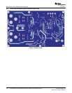
3JumpersandControlUtilities
3.1ClockFrequencyChangeJumper
3.2SPDIF/PSIAUtilizationJumpers
3.3DataRoutingJumpers
www.ti.com
JumpersandControlUtilities
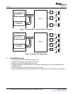
IntheabsenceofdigitalsignalsourceADC(PCM1808)maybeusedtoconvertananalogaudiosignalto
digitalsignalandprovideittoTAS5704.DIR9001stillprovidesclockstoADCinthisprocess.The
frequencyoftheoscillatorselectedforDIR9001determinsethesamplingfrequencyintheabsenceof
digitalsignal.IftheOSCis24MHzthesamplingfrequencywillbesetat96kHzandiftheOSCisselected
tobe12MHzthesamplingfrequencywillbedefaultedto48kHzwhenthereisnosignalonSPDIFinput
terminals.ADCisanadditionalfeaturetothisboardtoprovideflexibilityinsourcingaudiosignalto
TAS5704.PleasereviewthedatasheetofPCM1808fordetaildescriptionoftheADConthisEVM.
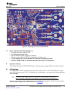
Afterconnectingtheloudspeakers(loads),powersupply,anddataline,poweruptheVINpowersupply.
ThenpowerupthePVCCpowersupply.ItisrecommendedtosetthePVCClevelto10voltsandthen
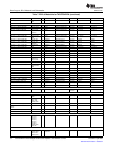
rampitupto20voltstoverifythecableconnectionfunctionality.Itisrecommendedtosetthegainto
–3dBatstartbyhavingbothGAIN(GAIN0andGAIN1)jumpersinserted.Notethatthegainsettings
markedontheEVMarenotcorrect.PleaseseeTable3onthenextpageforthecorrectsettings.Having
jumpersFM0andFM1insertedandFM2removedsetsthedataformatforthedevicetoI2Sformat.Make
suretheSPDIFformatjumpers,FMT0andFMT1areremovedtosetthereceiverformattoI2S.Itis
importanttonotethatadeviceRESET(S2onthetopoftheboardlabeledMASTERRESET)needstobe
appliedaftereachgain,format,orconfigurationchangeinorderforthedevicetolatchinthenewsettings.
Finally,installjumpersCFG1andCFG2intheConfigControltoselect2-CH-BTL-ADmode.
JP1:Inthepresenceofavaliddigitalsignalinput,whenSPDIFlockoccurs,theusermayuseJP1to
changeLRclockandBITclock.Whenashuntisinserted,theSCKO=512Fsandwhentheshuntis
removedtheSCKO=256Fs.DefaultisSCKO=256Fs.
IntheabsenceofavaliddigitalsignalDIR9001clockoutputsswitchtothefrequencyofcrystal(Y1).Ifthe
crystalischosentobe24MHztheLRclockwillbe96KHzandifthecrystalischosentobe12MHztheLR
clockwillbe48kHz.
ThejumpersMCLK,LRCK,SCLK,SDATAallowtheusertoswitchbetweentheinternalclockanddata
sourcesandexternalclockanddatasourcesforinstancePSIA(fromAPinstrument).Thedefault
configurationofthesejumpersisSPDIFasitismarkedontheEVMwithawhitearrow.PSIAoutputsmay
beutilizedusingpins2and3ofthejumpers.Keepinmindthatpin3ofeachjumperisconnectedto
GND.Thus,theusermustpayattentiontothepolarityofthePSIAoutputcablesatthetimeofinsertion.
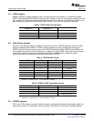
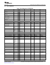
JumpersSDIN1,SDIN2:ThesejumpersenabletheusertoassignadatasourcetoTAS5704SDIN1and
SDIN2pins.SeeTable2.
Table2.TAS5704SDINxDataSource
JumperJP15:SDIN1JumperJP16:SDIN2SDIN1SourceSDIN2Source
PositionPosition
1-21-2ADCADC
1-22-3SPDIF/PSIASPDIF/PSIA
2-31-2SPDIF/PSIAADC
2-32-3SPDIF/PSIASPDIF/PSIA
SLOU224–April2008TA5704EVM4-ChannelDigitalAudioPowerAmplifierwithHardwareControl11
SubmitDocumentationFeedback