


13
Types of Support Structures
and Mounting
(continued)
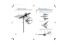
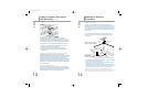
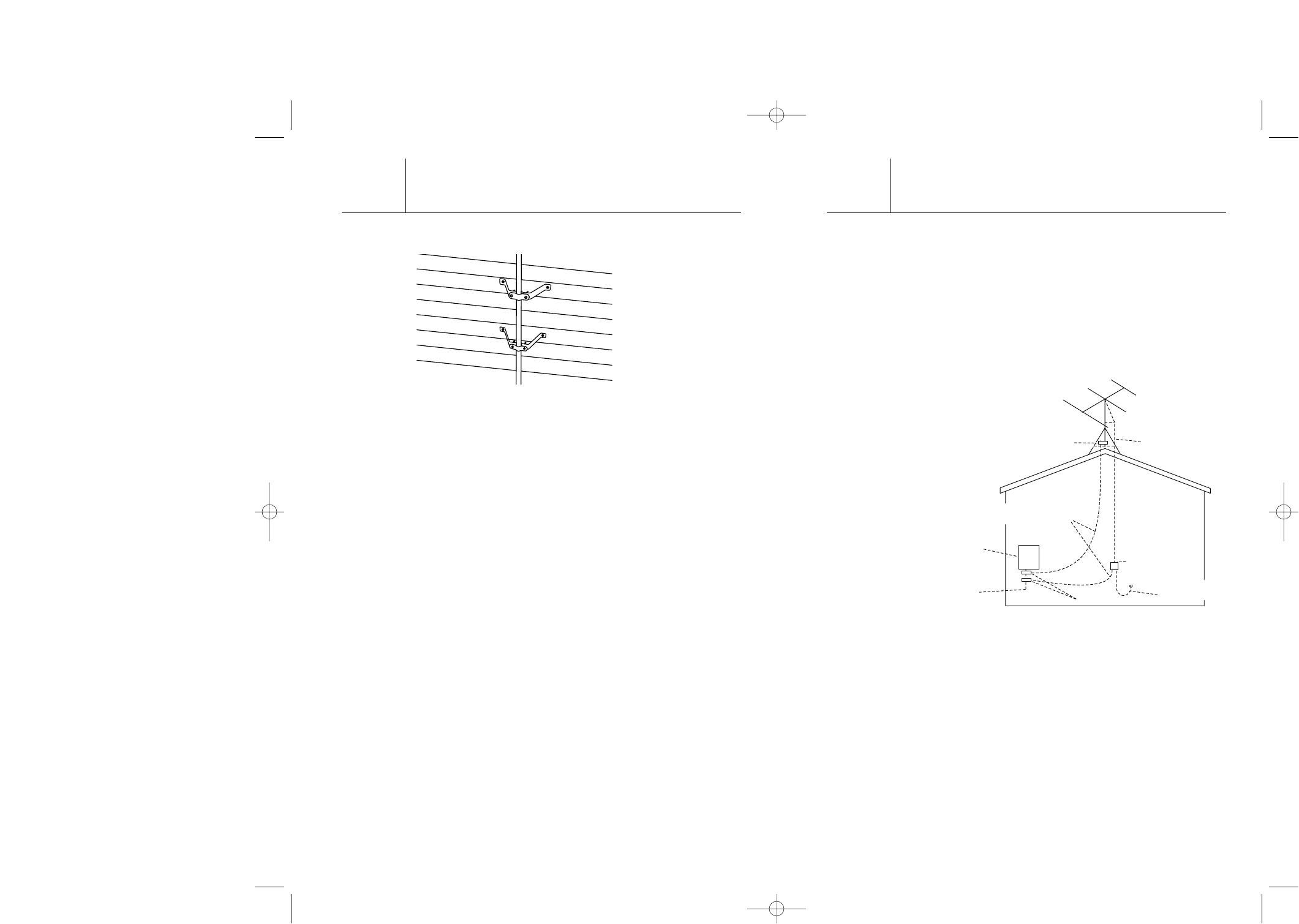
Wall Mount
Suggested height limitation: 10 feet above the rooftop.
An outside wall of your home is also an easy and convenient
mounting place, but the wall and fasteners that you use must be
strong enough to support the antenna in high winds. Ensure that
the brackets are securely fastened to a solid part of your wall.
1. Space the mounting brackets on an exterior wall – be sure
to clear roof eaves or any other obstacles.
2. Secure the brackets to the wall using the 4 lag screws.
3. Insert the mast between the saddles and secure with the
nuts and bolts.
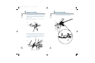
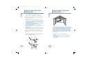
Tripod Mount (not included) - Used on peaked and flat roofs
Suggested height limitation: 10 feet above the rooftop.
Installation involving a tripod mount and a mast should be guyed if
the mast is ten feet or more. The tripod mount must be securely
anchored to the roof as should the guy wires. Apply roofing
compound around the base of the brackets, screws and eyebolts to
weather proof the holes in the roof. Try to lag bolt the legs to the
roof rafters. If not, install wood plates in the attic and install bolts
to secure the mount.
Telescopic Mast (not included)
The minimum safe diameter of the mast is 1-1/4 inches for this
type of mount. Guy wires should be equally spaced in at least three
directions. Use at least three guy wires for each ten foot section
of mast. Make sure guy wires are spaced evenly apart.
TV36
14
Example of Antenna
Grounding
NOTE: Grounding the antenna and mast provides lightning protection for
the antenna and your TV set.
All outdoor antenna installations should be properly grounded. To
effectively protect the installation, the coaxial cable(s) should be grounded
before they enter the house. The grounding of the coaxial cable is made
using a “ground block” and copper wire (not supplied). For information and
the materials needed to ground your antenna installation, visit your local
electronics store.
If you are not sure how to install the grounding block and rod, please
consult your local retailer or TERK’S Technical Support Department at
1-800-942-8375.
1. Mount the 75 ohm grounding block or discharge unit as close as possible
to where the downlead enters the house.
2. The ground wires for both the mast and the downlead should be copper
or aluminum wire, number eight (8) or larger.
3. The downlead wire from the antenna to the antenna grounding block or
discharge unit and the mast ground wire should be secured to the house
with stand-off insulators, spaced from four (4) to six (6) feet apart.
NOTE: In the case of a “ground up” antenna installation, it may not be
necessary to ground the mast if the mast extends four or more feet into the
ground. Consult a TV serviceman for the proper depth in your location.
TV36
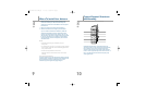
Antenna Lead
in Wire
Ground
Clamp
Electric
Service
Equipment
Antenna
Discharge Unit
(NEC Section 810-20)
Power Service Grounding
Electrode System
(NEC Art 250, Part H)
Ground
Clamps
Grounding Wire Conductors
(NEC Section 810-21)
NEC - National Electrical Code
Example of antenna grounding as per
National Electrical Code, ANSI/NFPA 70
Rain Drip Loop On
Lead-in To TV
T0436-TV36 Revise-OM.qxp 11/11/03 03:53 AM Page 13