


4
2 Connecting NEO to the World
NEO has a total of three different ports that are used to connect it to the world. Likely, the first port that will need to
be connected is the RS-232 port.
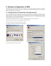
2.1 RS-232 Port
The RS-232 port is used for initial setup purposes only. It is a standard DCE pinout allowing a straight through DB9
cable to connect it to a computer or other terminal device for setup. Default baud rate is 19200,N81.
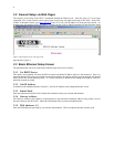
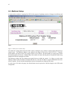
2.2 Ethernet Port
The Ethernet Port is used for setup of the NEO as well as for its operation from the consoles. Control of its relays is
handled through this port. The NEO sends multicast packets whenever status of one of its relays or inputs changes
allow for all users of the device to see real time changes in parallel. The port supports both 10 and 100 Mbps
operation of standard Cat 5 cable.
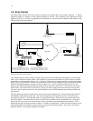
2.3 Relay/Input Ports
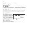
There are 10 RJ45 ports that are used to sense inputs and control external events. Each connector is connected to a
DPDT relay. Both sets of poles are brought out
to the connector allowing for two separate
circuits to be controlled by a single relay. Figure
1 shows the pin out of the rear RJ45s. “Relay1”
designates the pins on one half of the DPDT
relay and “Relay2” the other half. The relays are
rated for 1 Amp at 125VAC. The GND signal is
the signal ground of the device. The INPUT pin
is a diode blocked input that allows sensing of a
logic signal. The input range is 0-18 volts.
Exceeding the limits of either the Input or the
Relays is a violation of the warranty. The
manuals of the various Vega VoIP consoles should be consulted for programming the user interface buttons to
control the relays and sense the inputs of the NEO-10.
1 2 3 4 5 6 7 8 1) Relay1 N/O
2) Relay1 Common
3) Relay1 N/C
4) GND
5) INPUT
6) Relay2 N/C
7) Relay2 Common
8) Relay2 N/O
Connector View
Figure 1-NEO RJ-45 Connector Pinout