12
3.6 Echo Packet
The Echo Packet function allows the system to operate on networks that do not support multicast. A typical
application might be a number of radios spread throughout a network. Since multicast is not supported, the radio
adaptors (IP-223s or C-6200s) are programmed to send packets to a specific static IP address; the IP address of the
NEO-10 with Echo Packet enabled.
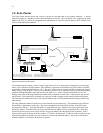
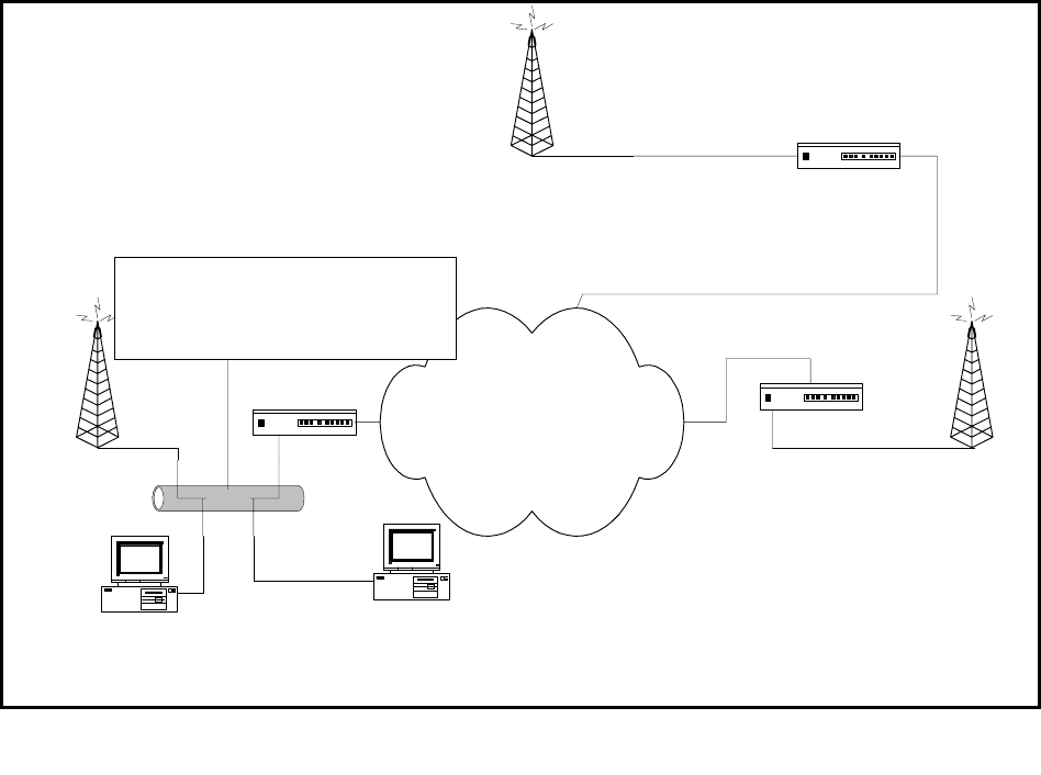
The Example shown in Figure 6 shows a typical usage of the NEO in an echo packet configuration. It shows three
radios, two of which are on other subnets. Since multicast is assumed to be blocked, only unicast UDP is available
to get audio two and from Radio Towers 2 & 3. The two C-Softs on the 10.6 subnet are able to monitor and control
Radio Tower 1 using multicast. However to reach Radios 2&3 the C-Softs send their traffic to the multicast address,
which the NEO then translates and sends as unicast to Radio 2 or 3. Receive traffic from Radios 2&3 are sent
directly to the NEO which then translates the packets back to multicast so each of the C-Soft consoles can monitor
the RX audio. This enables NEO to function as a gateway for other consoles on the same local network segment.
The local consoles transmit and receive the multicast address only and NEO translates and sends the packets to the
radio directly.
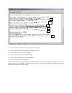
The setup parameters shown for each device on the network are an example only. The parameters of the NEO are
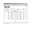
delineated by a dash between each value. The values correspond to the entry fields, per line, of the NEO setup
screen shown in Figure 7. Note that RX traffic is a single direction copy. Packets received are copied only to the
RX MCast address. Note that traffic received to the RX multicast address will be recopied back out. Since there
should only be one receive source on the network for a given channel, this should not present a problem. This is
depicted by the arrow at the top of the Rx columns. TX traffic is bi-directional. Traffic received as multicast is sent
to the unicast address and traffic received as unicast is copied to the multicast address. The ports are still used to
delineate channels. Unused ports should not be enabled.
Ethernet
Radio tower 1
10.6.100.100
225.8.11.83
RX:1054
TX:1072
Radio tower 2
Base:10.7.100.101
RX: 10.6.100.202 - 1055
TX: 10.6.100.202 - 1073
Radio tower 3
Base:10.8.100.102
RX:10.6.100.202 - 1056
TX:10.6.100.202 - 1074
C-Soft
10.6.100.200
Chan1: RX 225.8.11.83:1054 TX 225.8.11.83:1072
Chan2: RX 10.8.100.201:1055 TX 10.8.100.201:1073
Chan3: RX 10.8.100.200:1056 TX 10.8.100.200:1074
C-Soft
10.6.100.201
225.8.11.83
Chan1: RX 225.8.11.83:1054 TX 225.8.11.83:1072
Chan2: RX 225.8.11.83:1055 TX 225.8.11.83:1073
Chan3: RX 225.8.11.83:1056 TX 225.8.11.83:1074
Private WAN
Router
Router
Router
NEO-10
Base IP: 10.6.100.202
Echo Packet Settings:
1) 10.7.100.101-225.8.11.83-1055--10.7.100.101-225.8.11.83-1073
2) 10.8.100.102-225.8.11.83-1056--10.8.100.102-225.8.11.83-1074
3-10 are disabled.
Figure 6-Echo Packet Setup Example


