


9
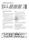
6. BREAKER
This is a resettable circuit breaker that monitors
the amount of current being drawn by the amplifier.
Under normal operating conditions, this should never
pop. An unusual condition may cause the breaker to
pop, such as a mains voltage surge occurring at the
same time as a peak amplifier output.
Turn the POWER switch off, and push the
BREAKER button in to reset the circuit breaker. Turn
the POWER switch back on and the amplifier should
resume normal operation. If the circuit breaker pops
again, something probably isn’t right.
• Make sure that the total impedance of the
speakers connected to the outputs is 2 ohms or
greater (per channel) in stereo mode, or 4 ohms
or greater in bridged mode.
• If the breaker pops right away, even with the
Level controls turned down and the speakers
disconnected, there may be something wrong
inside the amplifier. Refer to “Appendix A:
Service Info.”
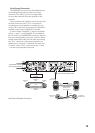
7. SPEAKER OUTPUTS
You have two options for connecting your
speakers: binding posts and Speakon connectors.
Normally, you would use either the binding posts
or the Speakon connectors. Since the connectors
are wired in parallel (e.g., CHANNEL 1 binding
post and Speakon are in parallel, and CHANNEL 2
binding post and Speakon are in parallel), you can
connect a speaker to each connector, as long as the
total impedance per channel is two ohms or more.
• Two 8 ohm speakers in parallel equals 4 ohms.
• Two 4 ohm speakers in parallel equals 2 ohms.
See “Output Wiring” on page 11 for information
on output connection wiring.
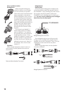
8. INPUTS
The Juice amplifiers give you two options for
connecting the input signal — XLR input connectors
and 1/4” TRS (Tip-Ring-Sleeve) connectors. These
inputs are in parallel, and are identical, electrically
speaking. You can connect either a balanced or an
unbalanced signal here.
Since these two inputs are in parallel, you
shouldn’t connect more than one source to the
INPUT 1 or INPUT 2 jacks. However, you can use
the unused input jack as a “Thru” connector, to
daisy-chain the signal to another amplifier. See
“Input Wiring” on page 10 for information on input
connection wiring.
9. SUBSONIC FILTER
Turn this switch on to engage a low-frequency
cutoff (high-pass) filter at 30 Hz. The Juice
amplifiers can amplify signals below 20 Hz, but
most speakers can’t reproduce frequencies that
low. By engaging the SUBSONIC FILTER, you allow
the amplifier to power only the frequencies that
you can hear. In addition, this filter can remove low-
frequency stage noise (footsteps) and accidental
microphone pops that could damage a loudspeaker.
10. CLIP LIMIT
The CLIP LIMIT switch is there to protect your
loudspeakers from the effects of clipping. It is
designed to be virtually transparent, meaning you
probably won’t even notice any audible difference
when the switch is turned on.
We recommend that you leave this switch on at all
times. However, if you are working at quiet levels, or
you have already placed a compressor/limiter in the
signal path, you can leave the CLIP LIMIT switch off.
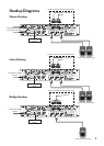
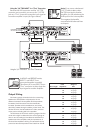
11. AMP MODE
This switch determines the input signal routing
within the amplifier. For most applications, you
will use the STEREO setting. However, some
applications might be better suited for using either
the MONO or the BRIDGE setting.
STEREO: This mode accepts separate left and right
inputs (A and B), and routes them to the CHANNEL
1 and CHANNEL 2 outputs. Each channel’s Level
control adjusts the gain for its own channel.
MONO: This mode accepts a single input (INPUT
1), and routes it to both the CHANNEL 1 and
CHANNEL 2 outputs. Each channel’s Level control
adjusts the gain for its own channel.
BRIDGE:
This mode accepts a single input (INPUT
1), and uses both amplifier outputs to double the
power to one speaker (or set of speakers). Use the
CHANNEL 1 Level control to adjust the gain (turn
the CHANNEL 2 Level control all the way down).
See “Output Wiring” on page 11 for information on
how to connect a speaker in Bridge mode.
GENERAL PRECAUTIONS AND
CONSIDERATIONS
Rack Mounting
The Juice amplifiers are designed to be mounted
in a standard rack. They require two rack spaces
(2U = 3.5”). They also require 15.75” depth inside
the rack, including the rear support brackets. When
designing your rack, put the heavier items at the
bottom and the lighter items toward the top.
Secure the front panel of the amplifier to the
front of the rack using four screws with soft washers
to prevent scratching the panel. In addition,
because of the weight of the amplifier, you must
secure the rear support brackets of the amplifier to
the back of the rack. You could use a support rail or