


C M Y CM MY CY CMY K
7
TM
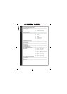
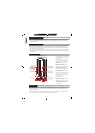
5.1: AC POWER REQUIREMENTS
AC Power Requirements
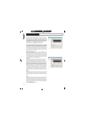
VNET“ products are equipped with Neutrik Powercon“ mains connectors which mate with the Neutrik NAC3FCA Cable
connector, quick lock with a securing lever for power-in. This AC mains connector is supplied with each VNET“ product. The
amplifier operates between the ranges of 100 to 240 Volts; the auto ranging power supply detects the mains voltage automatically
and configures accordingly. Replace the mains fuse only with the same T10A HBC type supplied by Tannoy under part number
3461 0919.
5.2 COOLING
Do not install this equipment in an enclosed space. Do not limit free ventilation and movement of air around the back panel.
Ensure that there is at least 100mm (4") of space around all sides of the product for ventilation. An efficient switch mode power
supply has less weight, less current draw and more efficient mechanical cooling; meaning that no fans are required. In an area
with a relatively high ambient temperature the heatsink can reach temperatures of up to 65 degrees C, this is perfectly normal.
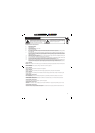
5.3 LED FUNCTIONS
On switch on all of the LED s will illuminate instantaneously. The first to go off is the green signal LED after about 1 second.
The red limit LED will flash for 5-10 seconds, this is the unit performing a self diagnostic test. During this initial few seconds
the audio is muted until the red LED stops flashing & the blue power LED is the only LED left illuminated.
After the self diagnostic test is performed, the unit is ready to pass audio. When audio is detected the green signal LED will
illuminate. If at any time the Red LED flashes this indicates that the DSP is taking corrective action by applying limiting to either
the LF or HF channels (or both). Regular flickering of the Limit LED is perfectly acceptable; do not allow the limit LED to stay
on constantly for any sustained length of time (reduce the gain).
Fast regular flashing of the red LED indicates that the DSP is taking protective action; the input will be automatically attenuated
to avoid over driving, if this occurs the operator should reduce the input gain from the source. If the gain is not reduced the
unit will eventually be shut down by the DSP.
The blue Network Find LED on the front of the cabinet (behind the grill) can only be illuminated by activation from within the
software interface. When activated the LED will flash intensely as an aid to locate and identify loudspeakers connected on
the network. The red limit LED on the back panel also doubles as a network find LED duplicating the function of the blue front
mounted LED.
5.4 LIMITERS
The limiters are carefully set-up to preserve the loudspeakers dynamic headroom by allowing short term transients to pass;
audible degradation in sound will only become apparent when the limit indication is on constantly. The limiting functions will
protect the amplifier from long term overheating by attenuating the driving voltage to the drive units. If used irresponsibly
(constant hard clipping) sound quality will be compromised. In extreme cases drive units may also be damaged.
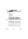
5.5: AUDIO CONNECTIONS
Audio Connections
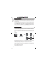
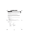
The signal input & link connectors are fully balanced. SIGNAL XLR CONNECTOR
When connecting a balanced signal be sure to wire Hot (+) Pin 2
to the following standard:- Cold (-) Pin 3
Shield (GND) Pin 1
In a standard balanced interconnection there are two signal conductors and a shield. The shield is normally referenced to
ground at one or both ends.˚ Many times the shield is lifted at one end, usually at the input to eliminate "ground loops" or
noise.˚The problem with this approach is that while it may reduce hum, the shields act as radio antennas and pickup radio
frequency interference from the environment.˚
Multiple enclosures may be driven from a single audio source; simply plug the signal source output into the first XLR input
socket, and patch that speakers XLR link to the next speakers XLR input socket & so on.