


C M Y CM MY CY CMY K
13
TM
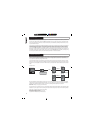
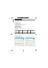
PodWare communicates with VNET“ using a serial COM port as a
network connection. When a network connection is open and actively
connected to a compatible device, the system is said to be On Line .
Whilst On-line, you can control the connected device in real time , and
continuously receive status information from the device. When going online,
the application will take a few seconds while it copies the settings in the
device to the control panel. (See parameter synchronisation)
˚
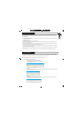
To go On-line, you can either select Device/Online from the menu, or press
the Online toolbar button, which is a red triangle. If all is well, the triangle
will turn green, indicating that you are On-line .
You can however operate your system without going On-line. You can
send the current controls settings to a device using Device/Send (See
Menus), or by clicking the Send toolbar button (see Toolbar). These
actions clearly still require a network connection to be present.
Parameter Synchronisation
PodWare aims to always ensure that the control settings in the virtual
control panel are always a faithful representation of the settings in the
connected device. To achieve this, the parameters in the device are copied
to the control panel when going online. This takes a few seconds to
complete (see Communications). Whilst online, any changes to the control
settings will result in changes in the stored parameters in the devices, thus
retaining synchronisation. When a file is opened online, the new settings
are not only set in the control panel; they are also transferred to the device.
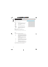
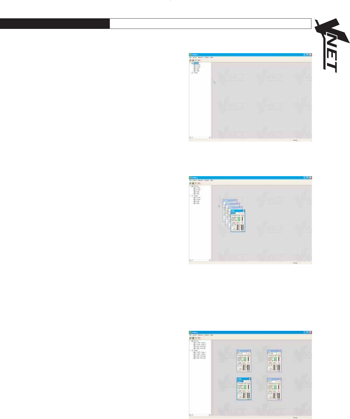
Controlling Devices
When online the tree menus will show the connected VNET“ speakers
on the network. Double clicking on the model on the tree view will open
the control panel for each respective device. Each open panel will also
appear on the tree view under panels . When online, Podware gathers
information from the connected devices. Any parameters which have been
adjusted by the user in previous sessions will be shown.
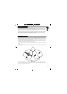
Each control panel can be positioned on the screen to represent its actual
location position in the venue. When saving data the control panels
co-ordinates are also saved so that it appears in the same location on the
screen when data is recalled (see saving & recalling data)
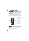
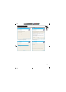
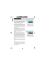
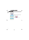
The panels shown on the opposite screenshot allows you to view what is
going on inside the VNET“ product. As well as a mute button, there are
limiter meters which indicate signal level relative to the limiter threshold
setting, input level meter, clip indicators which show when an amplifier is
clipping the signal due to overly high levels, driver status indicators showing
the status of each driver ( A is LF & B is HF), a temperature meter showing
the temperature of the amplifiers, and a ’Status’ indicator showing when
an amplifier is protecting itself from damage due to abnormal operating
conditions.
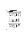
The arrow button (>>) at the top right hand side of the control panel will
expand the control panel to reveal a host of parameters which can be
viewed & adjusted.
8.0 SOFTWARE OPERATION