


5
the differential mode. In differential
operation the (A) and (B) center
conductors carry the signal and shielded
preamp ground, and the shields are tied to
the SR554 chassis. The (A) and (B)
cables should be twisted together to
prevent inductive pick-up.
For most experiments it is preferable to
use the SR554 in the buffered mode. If
the preamplifier is used in the bypass
mode, care must be taken to not load the
output. The output resistance of the
transformer is at least 5 kΩ (for a 0 Ω
source) and is typically 10,000 times the
input resistance. Therefore, a 50 Ω
source impedance will become 500 kΩ. If
the instrument that the SR554 is
connected to has an input impedance of 1
MΩ, 1/3 of the signal is lost. Any
significant cable capacitance will create a
low-pass filter with this output resistance
as well, so short cables should always be
used.
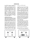
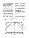
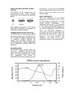
GAIN OF SR554
The actual gain of the SR554 is a function
of the source impedance, frequency and
the set gain. In the bypass mode (x100),
the gain will be affected by loading on the
output. The gain is fairly flat over a range
of input impedances (<10 Ω) and
frequencies (5 Hz-10 kHz). The actual
gain can be determined from the
amplitude-frequency response curves on
page 4. The plot assumes operating the
SR554 in the buffered mode or with no
loading on the output in the bypassed
mode.