


7
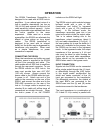
USING THE SR554 WITHOUT AN SRS
LOCK-IN
The SR554 can be powered with an
external power supply. Power is applied
through the 9 pin connector as described
below.
PIN
VOLTAGE CURRENT
1 +20 V 100 mA
6 -20 V 100 mA
7,8 Ground
Both voltages are required. Pins 7 and 8
should be tied together and grounded. All
other pins should be left open.
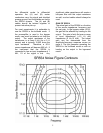
COMMON MODE REJECTION RATIO
The SR554 has an extremely high CMRR
at low frequencies (up to 160 dB below 10
Hz). It drops off at higher frequencies due
to capacitive coupling between the
primary and secondary windings and
reduced signal gain. See the graph below
for the relationship between CMRR and
frequency.
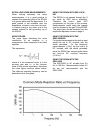
RADIATED NOISE
The SR554 reduces radiated noise from
the lock- in amplifier’s input by 40 dB
(100x) over most frequencies (DC to 500
MHz). To minimize radiated noise, a thick
(low impedance) wire should be
connected from the ground plug to a quiet
ground point. If a ground is not available
near the experiment, connect a wire to the
lock-in using a lug under one of the
chassis screws.
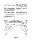
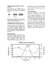
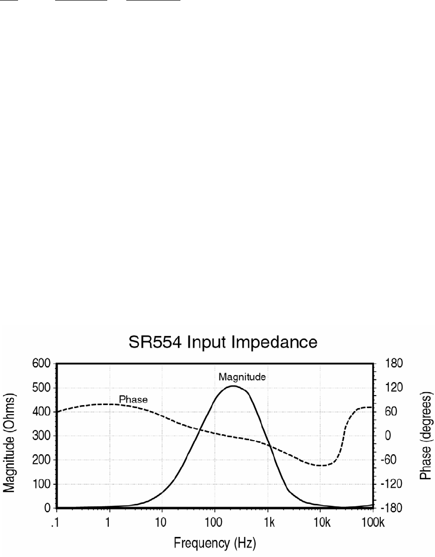
INPUT IMPEDANCE
The input impedance of the SR554
appears as a combination of 0.5 Ω and
0.5 H (in series) in parallel with 1.6 µF and
several parasitic impedances. The
transformer primary has a DC resistance
of 0.2 Ω and a primary inductance of 0.5
H. The secondary has a DC resistance of
3 kΩ and a capacitance of about 160 pF.
When the secondary impedance is
converted over to the primary side of the
transformer by the turns ratio (1:100), the
0.5 Ω, 0.5 H and 1.6 µF values are
obtained. The actual values of the
magnitude and phase of the input
impedance is shown in the graph below.