


6
EXTRA LOW NOISE MEASUREMENTS
When making extremely low noise
measurements, it is a good practice to
connect the grounding plug of the SR554
to a ground point near the experiment. If a
good ground is not available near the
experiment, connect a wire from the lock-
in chassis (using a lug under one of the
chassis screws) to the grounding lug of
the SR554.
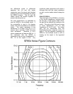
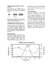
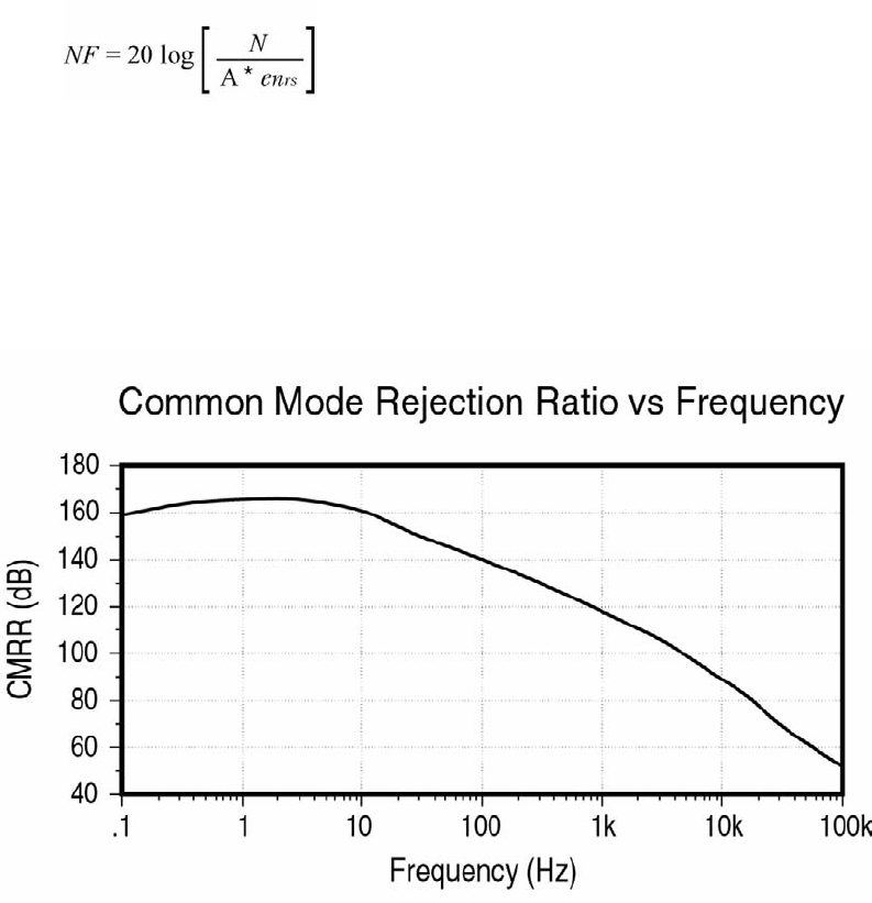
NOISE FIGURE
The noise figure describes the noise
contribution of an amplifier in a
measurement when compared to an ideal
amplifier.
The expression:
where N is the measured noise, A is the
pre-amp gain and e
nrs is the Johnson
noise of the source impedance, describes
the noise figure contours shown below.
The optimum operating frequency can be
determined from this graph.
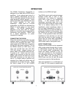
USING THE SR554 WITH SRS LOCK-
INS
The SR554 is not sensed through the 9
pin cable by SRS lock-in amplifiers.
Therefore the lock-in does NOT
compensate for the gain of the preamp.
Measurements made using the preamp
must be divided by the gain of the SR554.
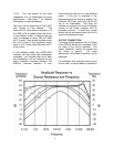
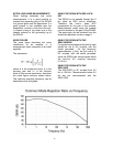
The actual gain can be obtained from the
amplitude response curves on page 4.
USING THE SR554 WITH THE
SR810/830/850
For typical measurements the lock-in input
should be set to AC coupled, with the
shield grounded. For low frequency
measurements (<1Hz), set the lock-in to
DC coupled, with the shield grounded,
since the SR554 can sense signals below
the lock-in’s AC coupling frequency
(0.16 Hz).
USING THE SR554 WITH THE
SR510/530
The SR510/530 is AC coupled from 0.5
Hz to 100 kHz. Measurements below 0.5
Hz are not recommended with the
SR510/530.