


4
US
Getting Started
Unpacking
Check that you received the following items with the
receiver:
• FM wire antenna (1)
• AM loop antenna (1)
• Remote commander (remote) (1)
Model Remote
STR-DE535 RM-LJ302
STR-DE435 RM-PP402
• LR6 (size-AA) batteries (3) (STR-DE535 only)
• R6 (size-AA) batteries (2) (STR-DE435 only)
• Operating Instructions of the remote (1)
• Operating Instructions of CONTROL A1 II (1)
(STR-DE535 only)
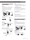
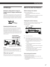
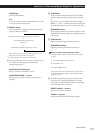
Inserting batteries into the remote
Insert the LR6 (STR-DE535) or R6 (STR-DE435) (Size
AA) batteries with the + and – properly oriented in the
battery compartment. When using the remote, point it
at the remote sensor
(STR-DE535) or g (STR-
DE435) on the receiver.
For details, refer to the operating instructions supplied
with your remote.
You cannot operate the following buttons on the
RM-PP402 remote (STR-DE435 only)
• VIDEO2
• VIDEO3
• DVD
• PHONO
• SOUND FIELD A. F. D.
Notes
• Do not leave the remote in an extremely hot or humid
place.
• Do not use a new battery with an old one.
• Do not expose the remote sensor to direct sunlight or
lighting apparatuses. Doing so may cause a malfunction.
• If you don’t use the remote for an extended period of time,
remove the batteries to avoid possible damage from
battery leakage and corrosion.
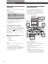
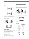
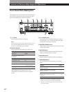
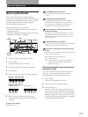
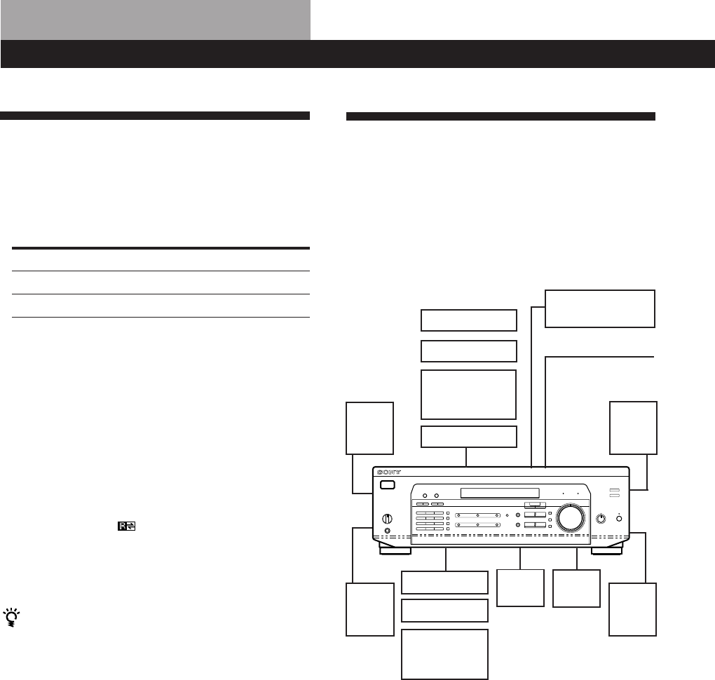
Hookup Overview
The receiver allows you to connect and control the
following audio/video components. Follow the
hookup procedures for the components that you want
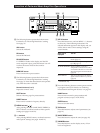
to connect to the receiver on the pages specified. To
learn the locations and names of each jack, see “Rear
Panel Descriptions” on page 28.
AM/FM antenna
DVD player/AC-3
decoder
Front
speaker
(L)
Speaker
System
Hookups (7)
Antenna Hookups (5)
Front
speaker
(R)
Rear
speaker
(L)
Rear
speaker
(R)
CD player
MD/Tape deck
Turntable
(STR-DE535
only)
Center
speaker
Active
woofer
Video Component
Hookups (6)
TV monitor
TV tuner
SAT (Satellite
receiver)/LD
player
VCR
Audio Component
Hookups (5)
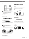
Before you get started
• Turn off the power to all components before making
any connections.
• Do not connect the AC power cords until all of the
connections are completed.
• Be sure to make connections firmly to avoid hum
and noise.
• When connecting an audio/video cable, be sure to
match the color-coded pins to the appropriate jacks
on the components: Yellow (video) to Yellow; White
(left, audio) to White; and Red (right, audio) to Red.