


9
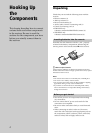
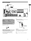
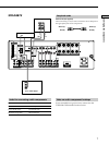
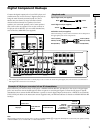
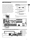
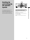
Hooking Up the Components
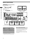
SIGNAL GND
DIGITAL
MD/DAT OUT
MD/DAT IN
TV/SAT IN
DVD/LD IN
OPTICAL
COAXIAL
DVD/LD
IN
AUDIO IN AUDIO IN AUDIO OUT
AUDIO
OUT
AUDIO OUTAUDIO IN AUDIO IN
VIDEO OUT
VIDEO IN VIDEO IN VIDEO IN VIDEO IN
FRONT
VIDEO OUT
SWITCHED 120W/1A MAX
AC 120V 60Hz
4
Ω 8Ω
VIDEO OUT
S-VIDEO
OUT
S-VIDEO
OUT
S-VIDEO
IN
S-VIDEO
IN
S-VIDEO
IN
CTRL S
IN
CTRL S
OUT
CTRL S
OUT
CTRL S
STATUS IN
ANTENNA
COAXIAL
FM
75
Ω
SUB
WOOFER
INOUT
TAPE
MONITOR
TV/SAT DVD/LD
VIDEO 2 VIDEO 1
AC OUTLET
IMPEDANCE
SELECTOR
R
L
R
L
R
L
SURROUND CENTER FRONT
IMPEDANCE USE 8 – 16Ω IMPEDANCE USE 4 – 16Ω
R
L
R
L
SPEAKERS
R
L
SUB
WOOFER
MULTI CH IN
FRONT SURROUND
CENTER
IN INOUT
CD/SACD
IN
PHONO
R
L
R
L
MD/DAT
CONTROL A1
2ND ROOM
AM
U
R
L
VIDEO
OUT
R
AUDIO
OUT
OUTPUT
L
DIGITAL
COAXIAL
OUTPUT
VIDEO
OUT
R
AUDIO
OUT
OUTPUT
L
DIGITAL
OPTICAL
OUTPUT
DIGITAL
OPTICAL
OUTPUT
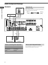
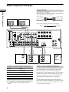
DVD/LD
VIDEO IN
DIGITAL
DVD/LD IN
(COAXIAL)
(OPTICAL)
DOLBY DIGITAL
RF OUT
VIDEO OUT
? / 1
DISPLAY
DIMMER
ON SCREEN
MEMORYSHIFTFM MODE FM AM
PRESET
TUNING
TUNING
–
+
–
+
MULTI CHANNEL DECODING
A.F.D.
SOUND FIELD
MULTI /2CH A. DIRECT
DIGITAL CONCERT HALL
EQUALIZER
MUTING
INPUT MODE
MODE
2ND ROOM
FUNCTION
6.1 CH DECODING
CINEMA STUDIO EX
AA
MODE 2CH
PHONES
VIDEO 3 INPUT
VIDEO L AUDIO R
SPEAKERS
EQ
SURR
LEVEL
SET UP
NAME
ENTER
BBC
MASTER VOLUME
+
–
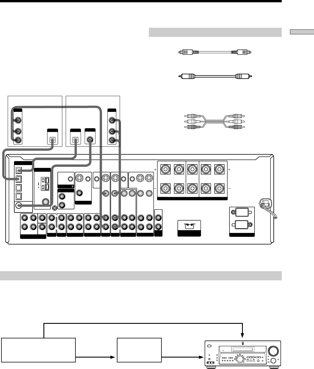
Required cords
Optical digital cords (not supplied)
Coaxial digital cord (not supplied)
Audio/video cords (not supplied)
When connecting a cord, be sure to match the color-coded pins to
the appropriate jacks on the components.
Connect the digital output jacks of your DVD player and
satellite tuner (etc.) to the receiver’s digital input jacks to
bring the multi channel surround sound of a movie
theater into your home. To enjoy full effect of multi
channel surround sound, five speakers (two front
speakers, two surround speakers, and a center speaker)
and a sub woofer are required. You can also connect an
LD player with an RF OUT jack via an RF demodulator,
such as the Sony MOD-RF1 (not supplied).
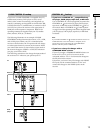
Digital Component Hookups
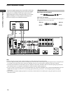
Example of LD player connected via an RF demodulator
Please note that you cannot connect an LD player’s DOLBY DIGITAL RF OUT jack directly to the receiver’s digital input
jacks. You must first convert the RF signal to either an optical or coaxial digital signal. Connect the LD player to the RF
demodulator, then connect the RF demodulator’s optical or coaxial digital output to the receiver’s OPTICAL or COAXIAL
DVD/LD IN jack. Refer to the instruction manual supplied with your RF Demodulator for details on DOLBY DIGITAL RF
hookups.
RF demodulator
LD player
Black Black
Yellow Yellow
Yellow (video) Yellow (video)
White (L/audio) White (L/audio)
Red (R/audio) Red (R/audio)
DIGITAL
DVD/LD IN
(COAXIAL)
or (OPTICAL)
Note
When making connections as shown above, be sure to set INPUT MODE (qa on page 27) manually. The receiver may not operate correctly
if INPUT MODE is set to “AUTO 2CH” or “AUTO MULTI CH”.
*
When making digital audio connections to a DVD player, connect to either the coaxial OR optical digital jacks, and not both. It is recommended to
make digital audio connections to the coaxial jack.
DVD or LD player (etc.)*
TV or satellite tuner