


10
GB
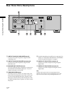
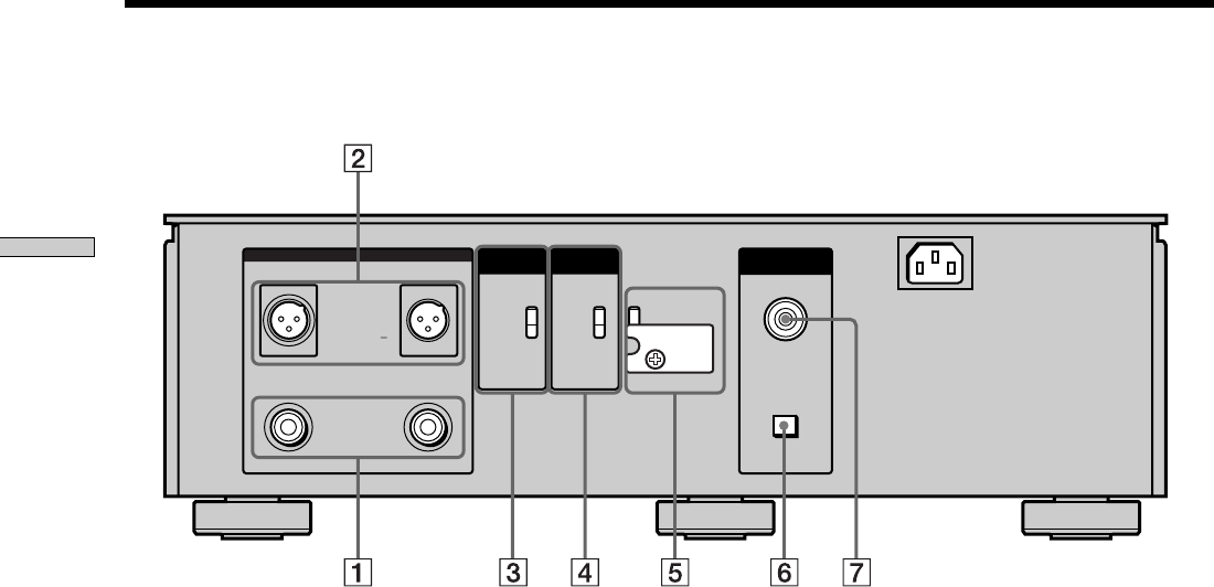
Location and Functions of Parts
5 Switches depending on amplifier to be connected. For
details, see “About the Switch Marked “STANDARD”
on the rear panel of the player” on page 6.
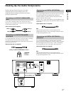
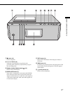
6 DIGITAL OUT (CD) OPTICAL connector (5)
Connect to an audio component using an optical
digital cable.
7 DIGITAL OUT (CD) COAXIAL connector (5)
Connect to an audio component using the coaxial
digital cable.
Note
Only the audio signals of the CD can be output from the
DIGITAL OUT connectors shown in 6 and 7. Those of the
Super Audio CD cannot be output through DIGITAL OUT.
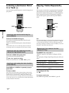
Rear Panel Parts Descriptions
COMMAND
MODE
BALANCED
OUT
COAXIAL
OPTICAL
DIGITAL OUT
CD
~AC IN
LINE OUT (ANALOG)
RL
RL
BALANCED
UNBALANCED
1:GROUND
2:HOT (+)
3:COLD ( )
ON
OFF
CD1
CD2
STANDARD
CUSTOM
TA - E1 / N1
1 LINE OUT (ANALOG) UNBALANCED jacks (5)
Connect to an audio component using the audio
connecting cord.
2 LINE OUT (ANALOG) BALANCED connectors (5)
Connect to an audio component using the XLR
(balanced) cord.
3 BALANCED OUT ON/OFF switch (5)
Set to ON when the audio component is connected to
the LINE OUT BALANCED connectors. In case of
another connection, set it to OFF.
4 COMMAND MODE selector
Normally set to CD1. When you connect a Sony CD
player other than this player, set to CD2. In this case,
you can control both the other Sony CD player and
this player with CD1/CD2 on the remote. Set to CD1
to control the other Sony CD player, or CD2 to control
this player.