


52
MZ-N505
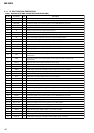
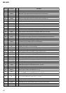
Pin No.
Pin Name
I/O Description
152 VSIOSC — Ground terminal (for the OSC cell)
153 DAVDD
—
Power supply terminal (for the built-in D/A converter) (+2.4V)
154 VREFL I Reference voltage input terminal (for the built-in D/A converter L-CH)
155 AOUTL
O
Built-in D/A converter (L-CH) output terminal
156 AOUTR
O
Built-in D/A converter (R-CH) output terminal
157 VREFR
I
Reference voltage input terminal (for the built-in D/A converter R-CH)
158 DAVSS
—
Ground terminal (for the built-in D/A converter)
159 ASYO
O
Playback EFM duplex signal output terminal
160 ASYI I Playback EFM comparison slice level input terminal
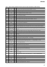
161 AVD1
—
Power supply terminal (for the DSP asymmetry system analog) (+2.4V)
162 BIAS
I
Bias current input terminal for the playback EFM comparison
163 RFI
I
Playback EFM the RF signal input from the RF amplifier
164 AVS1
—
Ground terminal (for the DSP asymmetry system analog)
165 PCO O Phase comparison output terminal for the playback EFM system master PLL
166 FILI
I
Filter input terminal for the playback EFM system master PLL
167 FILO O Filter output terminal for the playback EFM system master PLL
168 CLTV I Internal VCO control voltage input terminal for the playback EFM system master PLL
169 PEAK
I
Peak hold signal input of the light amount signal (RF/ABCD) from the RF amplifier
170 BOTM
I
Bottom hold signal input of the light amount signal (RF/ABCD) from the RF amplifier
171 ABCD I Light amount signal (ABCD) input from the RF amplifier
172 FE I Focus error signal input from the Focus error amplifier
173 AUX1 I Support signal (I
3
signal/temperature signal) input terminal (A/D input)
174 VC I Middle point voltage (+1.1V) input terminal
175 ADIO O Monitor output terminal of A/D converter input signal Not used
176 ADRT I A/D converter the upper limit voltage input terminal (fixed at “H” in this set)
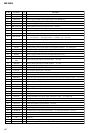
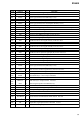
177 AVD2
—
Power supply terminal (for the DSP servo analog system) (+2.4V)
178 AVS2
—
Ground terminal (for the DSP servo analog system)
179 ADRB
I
A/D converter the lower limit voltage input terminal (fixed at “L” in this set)
180 SE
I
Servo signal monitor input terminal (A/D input) from the RF amplifier
181 TE
I
Tracking error signal input from the Tracking error amplifier
182 DCHG
—
Connecting terminal with the analog power supply of the low impedance (fixed at “H” in this set)
183 APC
I
Error signal input for the laser automatic power control (fixed at “H” in this set)
184 CKRF O Clock output terminal for the RF amplifier control Not used
185 DTRF O Data output terminal for the RF amplifier control Not used
186 XLRF O Latch signal output terminal for the RF amplifier control Not used
187 DVSS2
—
Ground terminal (for the DSP block)
188 DVDD2
—
Power supply terminal (for the DSP block) (+1.5V)
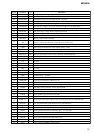
189 XTSL
I
Input terminal for the frequency set up of the system clock
“L”: 45.1584MHz, “H”: 22.5792MHz (fixed at “L” in this set)
190 DIN1
I
Input terminal of the record system digital audio signal
191 to
193
NC O D/A converter PWM signal output terminal Not used
194 DADT O Audio data output terminal Not used
195 ADDT
I
Data input from the external A/D converter
196 LRCK O L/R sampling clock signal (44.1KHz) output to the external A/D converter
197 XBCK O Bit clock signal (2.8224MHz) output to the external A/D converter
198 FS256
O
11.2896MHz clock signal output to the external A/D converter