1-14
MVE-9000 IM
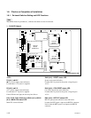
<Connector>
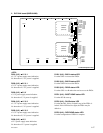
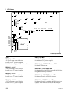
CN103 (A-4) : TERMINAL pin
This pin is connected to the main CPU control terminal
and used during maintenance.
Conforms to RS-232C.
CN401 (A-5) : TERMINAL pin
This pin is connected to the IEEE1394 control terminal and
used during maintenance.
Conforms to IEEE1394.
CN503 (A-5) : TERMINAL pin
This pin is connected to the COM CPU-1 control terminal
and used during maintenance.
Conforms to RS-232C.
CN703 (A-5) : TERMINAL pin
This pin is connected to the COM CPU-2 control terminal
and used during maintenance.
Conforms to RS-232C.
CN1002 (A-5) : TERMINAL pin
This pin is connected to the S-BUS CPU control terminal
and used during maintenance.
Conforms to RS-232C.
CN1003 (A-3) : ISP common connector
Used only for production in the assembly factory. Used for
program writing into the JTAG device with ISP.
<TEST terminal>
E1 (E-5), E2 (E-1), E3 (C-3), E4 (A-5), E5 (A-1) :
GND terminal
Use this terminal as the earth point for measuring the
respective check terminals.
TP1 (A-1) :
++
++
+3.3 V check terminal
+3.3 V measuring terminal.
TP23 (B-1) :
++
++
+12 V check terminal
+12 V measuring terminal.
TP1301 (A-1) :
++
++
+5 V check terminal
+5 V measuring terminal.
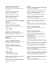
<LED on the CPU-DR module> : Main CPU
D10 (green) (A-1) : RUN status LED
RUN status indication.
Lit when the CPU-DR module starts operating.
D12 (green) (A-4) : CD (Card Detect) status LED
Lit when the CPU-DR module is inserted correctly into the
parent board.
D13 (green) (A-1) :
++
++
+2.5 V
Indicates the statue of the +2.5 V power that is generated
by the VCC (CORE) and supplied to the CPU-DR module.
Lit while the specified power is turned on.
D14, D15, D16, D17 (A-3) (green) : STATUS1 to
STATUS4 status LED
Used for maintenance purpose. Only the STATUS1 LED is
lit in normal operation.
D18 (green) (A-4) :
++
++
+3.3 V
Indicates the statue of the VCC (I/O) power that is sup-
plied to the CPU-DR module.
Lit while the specified power is turned on.
D19 (green) (A-4) : CORE status LED
Indicates the statue of the VCC (CORE) power that is
supplied to the CPU-DR module.
Lit while the specified power is turned on.
<Switch on the CPU-DR module> : Main CPU
SW1 (A-1) : RESET switch
Pressing this switch resets the CPU-DR module.
n
In some machines in which the CPU-DR module is
installed, the system reset may be activated.
SW2 (A-2) : MODE switch
8-pin DIP switch
Used only for production in the assembly factory. All
switches are set to OFF for normal operation.
Default setting when shipped from the factory is all OFF.


