


– 5 –
TABLE OF CONTENTS
1. SERVICING NOTE .......................................................... 6
2. GENERAL ........................................................................ 15
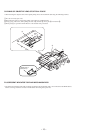
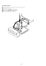
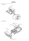
3. DISASSEMBLY
3-1. Glass ASSY......................................................................... 16
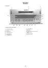
3-2. Front Panel ......................................................................... 16
3-3. Slider (CAM) ...................................................................... 17
3-4. Base Unit and BD Board .................................................... 17
3-5. SW Board and Loading Motor (M103) .............................. 18
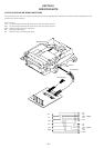
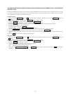
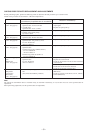
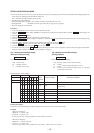
4. TEST MODE ..................................................................... 19
5. ELECTRICAL ADJUSTMENTS ............................... 23
6. DIAGRAMS
6-1. Circuit Boards Location ...................................................... 32
6-2. Block Diagrams
• BD Section ....................................................................... 33
• Main Section .................................................................... 35
6-3. Printed Wiring Board – BD Section –................................. 39
6-4. Schematic Diagram – BD (1/2) Section –........................... 41
6-5. Schematic Diagram – BD (2/2) Section –........................... 43
6-6. Schematic Diagram – Main (1/2) Section –........................ 45
6-7. Schematic Diagram – Main (2/2) Section –........................ 47
6-8. Printed Wiring Board – Main Section – .............................. 49
6-9. Schematic Diagram – Panel Section – ................................ 51
6-10. Printed Wiring Board – Panel Section – ........................... 53
6-11. Schematic Diagram – Connector Section –...................... 55
6-12. Printed Wiring Board – Connector Section – ................... 57
6-13. Schematic Diagram – BD Switch Section –..................... 59
6-14. Printed Wiring Board – BD Switch Section – .................. 59
6-15. Schematic Diagram – Encoder Section – ......................... 60
6-16. Printed Wiring Board – Encoder Section – ...................... 60
6-17. IC Block Diagrams ........................................................... 61
6-18. IC Pin Functions ............................................................... 64
7. EXPLODED VIEWS
7-1. Case and Back Panel Section .............................................. 67
7-2. Front Panel Section ............................................................. 68
7-3. Mechanism Section (MDM-5A) ......................................... 69
7-4. Base Unit Section (MBU-5A)............................................. 70
8. ELECTRICAL PARTS LIST ........................................ 71