


– 29 –
11. Rotate the – ˜ + knob until the waveform of the oscillo-
scope moves closer to the specified value.
In this adjustment, waveform varies at intervals of approx. 2%.
Adjust the waveform so that the specified value is satisfied as
much as possible.
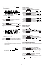
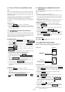
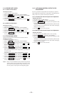
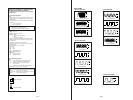
(Traverse Waveform)
12. Press the ENTER/YES button, and save the adjustment results
in the non-volatile memory. (“EFB =
SAVE” will be dis-
played for a moment.)
Next “EF MO ADJUST” is displayed. The disc stops rotating
automatically.
13. Press the § button and remove the disc.
14. Load the check disc (MD) TDYS-1.
15. Roteto – ˜ + knob and display “EF CD ADJUST”.
16. Press the ENTER/YES button and display “EFB = CD”.
Servo is imposed automatically.
17. Rotate the – ˜ + knob so that the waveform of the oscillo-
scope moves closer to the specified value.
In this adjustment, waveform varies at intervals of approx. 2%.
Adjust the waveform so that the specified value is satisfied as
much as possible.
(Traverse Waveform)
18. Press the ENTER/YES button, display “EFB =
SAVE” for
a moment and save the adjustment results in the non-volatile
memory.
Next “EF CD ADJUST” will be displayed.
19. Press the § button and remove the check disc (MD) TDYS-1.
Note 1 : MO reading data will be erased during if a recorded disc is
used in this adjustment.
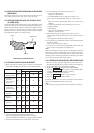
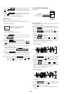
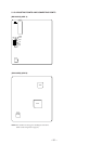
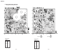
Note 2 : If the traverse waveform is not clear, connect the oscillo-
scope as shown in the following figure so that it can be
seen more clearly.
5-12. FOCUS BIAS ADJUSTMENT
Adjusting Procedure :
1. Load a test disk (MDW-74/AU-1).
2. Rotate the – ˜ + knob and display “CPLAY MODE”.
3. Press the ENTER/YES button and display “CPLAY MID”.
4. Press the MENU/NO button when “C1 = AD = ” is
displayed.
5. Rotate the – ˜ + knob and display “FBIAS ADJUST”.
6. Press the ENTER/YES button and display “ / a = ”.
The first four digits indicate the C1 error rate, the two digits
after [/] indicate ADER, and the 2 digits after [a =] indicate the
focus bias value.
7. Rotate the – ˜ + knob in the clockwise direction and find the
focus bias value at which the C1 error rate becomes 220 (Refer
to Note 2).
8. Press the ENTER/YES button and display “ / b = ”.
9. Rotate the – ˜ + knob in the counterclockwise direction and
find the focus bias value at which the C1 error rate becomes
approximately 220.
At this time, set the C1 error rate to about the same value set at
step 7.
10. Press the ENTER/YES button and display “ / c = ”.
11. Check that the C1 error rate is below 50 and ADER is 00. Then
press the ENTER/YES button.
12. If the “( )” in “ - - ( )” is above 20, press the EN-
TER/YES button.
If below 20, press the MENU/NO button and repeat the
adjustment from step 2.
13. Press the § button to remove the test disc.
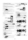
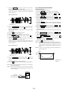
Note 1 : The relation between the C1 error and focus bias is as
shown in the following figure. Find points a and b in the
following figure using the above adjustment. The focal
point position C is automatically calculated from points a
and b.
Note 2 : As the C1 error rate changes, perform the adjustment us-
ing the average vale.
VC
A
B
Specification A = B
VC
A
B
Specification A = B
330 k
Ω
Oscilloscop
e
10pF
BD board
CN110 pin
3
(TE)
CN110 pin
1
(VC)
C1 error
approx.
220
b
c a Focus bias value
(F. BIAS)