


7
Location and Function of Parts
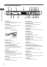
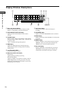
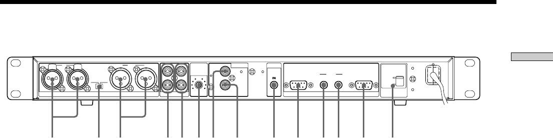
Rear of the Recorder
1 ANALOG (BALANCE) input terminal (XLR type)
Inputs as an analog signal the sound of the component
connected by an XLR connecting cable.
2 OUTPUT LEVEL (BALANCE) selector
Changes the output level of the BALANCE.
3 ANALOG (BALANCE) output terminal (XLR type)
Outputs as an analog signal the contents of the MD of
this recorder to the component connected by an XLR
connecting cable.
4 ANALOG (UNBALANCE) input jacks
Inputs as an analog signal the sound of the component
connected by a pin type connecting cable.
5 ANALOG (UNBALANCE) output jacks
Outputs as an analog signal the contents of the MD of
this recorder to the component connected by a pin type
connecting cable.
6 ANALOG INPUT LEVEL control
Can adjust the level of analog input in a range of _∞ ~
+15 dB.
Normally, this control is used in the position (0 dB) of
center click.
7 DIGITAL COAXIAL input jack
Inputs as a digital signal the sound of the connected
component.
8 DIGITAL COAXIAL output jack
Outputs an a digital signal the contents of the MD of
the recorder to the connected component.
9 CONTROL-S jack
Connects the remote or control equipment.
If the plug is connected to the jack, the remote sensor
does not receive infrared rays.
0 PARALLEL connector
(D-sub 9-pin female)
Connects a component with simple circuits for the
remote operations of the functions preset in the
recorder.
!¡ RELAY OUT connector
!™ REELAY IN connector
Plays or records successively by connecting multiple
recorders and sending a control signal.
!£ RS-232C connector
(D-sub 9-pin male)
Connects a component that controls the recorder from
outside.
!¢ VOLTAGE SELECTOR
(Except for the USA/CA models.)
Select 120V or 230V according to the local power line
voltage. (Refer to page 2)
ANALOG(BAL)
OUTPUT
LEVEL
LINR L
L
5
010
OUT
OUT
OUT
ANALOG(UNBAL)
ANALOG
INPUT
LEVEL
DIGITAL
COAXIAL
IN
IN
IN
PARALLEL
RELAY
REMOTE
OUT IN
RS-232C
R
R
+4dBu -10dBu
CTRL-S
PUSH PUSH
1 2 6 9 q; qaqs qd7 83 45
VO LTAGE
SELECTOR
230V
120V
qf