


56
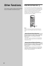
Rear Panel Terminal Functions
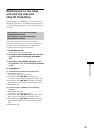
Relay Playback
Carry out steps 1 to 4 with all recorders connected
1 Press MENU/NO twice.
“Setup Menu” appears in the display.
2 Turn AMS (or press ./> repeatedly) until
“Relay” appears in the display; press AMS or YES.
3 Turn AMS (or press ./> repeatedly); select
“Play” ; press AMS or YES.
4 Press MENU/NO.
5 Start play on the first unit.
6 When the first recorder finishes play, the second
recorder begins play.
7 Play will continue in the same way for all other
recorder if a cable is connected to the RELAY IN
terminal.
Note
For the relay signal to be received and playback to begin in
all recorders, the following conditions must be satisfied.
• A disc that is able to play back must be in the recorder.
• The recorder must be stopped.
• The recorders must not be in “Edit Menu” or “Set up
Menu”.
If REPEAT is set, the control signal is not transmitted and
relay playback cannot be made.
Relay Recording
Carry out steps 1 to 4 with all recorders connected
1 Press MENU/NO twice.
“Setup Menu” appears in the display.
2 Turn AMS (or press ./> repeatedly) until
“Relay” appears in the display; press AMS or YES.
3 Turn AMS (or press ./> repeatedly); select
“Rec” ; press AMS or YES.
4 Press MENU/NO.
5 Start recording on the first unit.
6 When the first recorder finishes recording, the
second recorder begins recording.
7 Recording will continue in the same way for all
other recorders if a cable is connected to the RELAY
IN terminal.
Note
For the relay signal to be received and recording to begin
in all recorders, the following conditions must be satisfied.
• A recordable disc must be in the recorder.
• The recorder must be set input selector in accodance
with the connection to the input terminal.
• The recorder must be stopped.
• The recorders must not be in “Edit Menu” or “Set up
Menu”.
Relay recording is always at “New Track Rec.”
In relay recording, it is not possible to record overwrite.
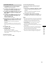
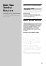
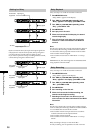
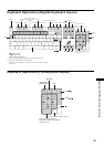
Cabling for Relay
ANALOG(BAL)
OUTPUT
LEVEL
LINR L
L
5
010
OUT
OUT
OUT
ANALOG(UNBAL)
ANALOG
INPUT
LEVEL
DIGITAL
COAXIAL
IN
IN
IN
PARALLEL
RELAY
REMOTE
OUT IN
RS-232C
R
R
+4dBu -10dBu
CTRL-S
PUSH PUSH
ANALOG(BAL)
OUTPUT
LEVEL
LINR L
L
5
010
OUT
OUT
OUT
ANALOG(UNBAL)
ANALOG
INPUT
LEVEL
DIGITAL
COAXIAL
IN
IN
IN
PARALLEL
RELAY
REMOTE
OUT IN
RS-232C
R
R
+4dBu -10dBu
CTRL-S
PUSH PUSH
ANALOG(BAL)
OUTPUT
LEVEL
LINR L
L
5
010
OUT
OUT
OUT
ANALOG(UNBAL)
ANALOG
INPUT
LEVEL
DIGITAL
COAXIAL
IN
IN
IN
PARALLEL
RELAY
REMOTE
OUT IN
RS-232C
R
R
+4dBu -10dBu
CTRL-S
PUSH PUSH
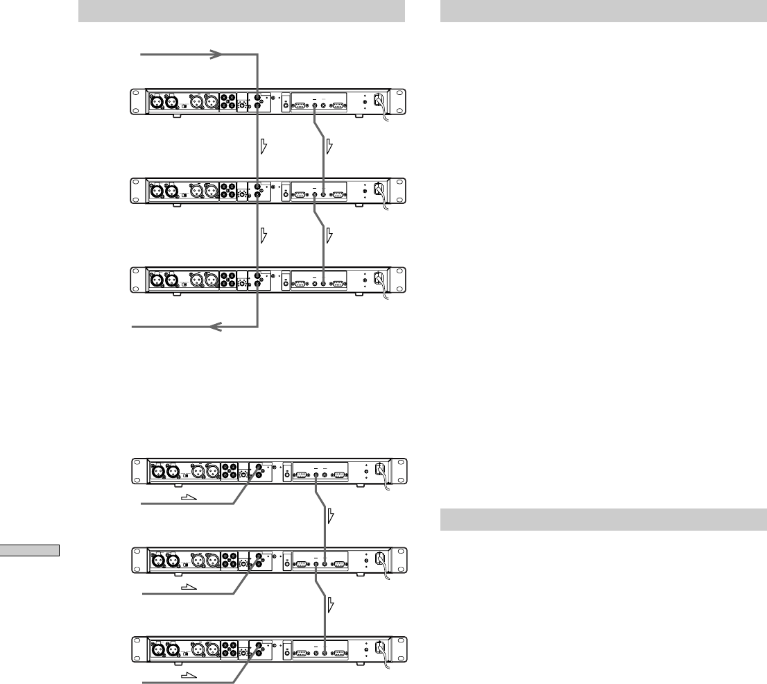
Input signal
Relay signal
Output signal
From divide
equipment
To mixer
By the connection above, the input and output signals are
ralayed, but for reasons of the system, the input signal is
cut off for about 2 seconds when recording is relay.
If you want to perform overlap recording without a blank,
connect the input signal as shown below.
ANALOG(BAL)
OUTPUT
LEVEL
LINR L
L
5
010
OUT
OUT
OUT
ANALOG(UNBAL)
ANALOG
INPUT
LEVEL
DIGITAL
COAXIAL
IN
IN
IN
PARALLEL
RELAY
REMOTE
OUT IN
RS-232C
R
R
+4dBu -10dBu
CTRL-S
PUSH PUSH
ANALOG(BAL)
OUTPUT
LEVEL
LINR L
L
5
010
OUT
OUT
OUT
ANALOG(UNBAL)
ANALOG
INPUT
LEVEL
DIGITAL
COAXIAL
IN
IN
IN
PARALLEL
RELAY
REMOTE
OUT IN
RS-232C
R
R
+4dBu -10dBu
CTRL-S
PUSH PUSH
ANALOG(BAL)
OUTPUT
LEVEL
LINR L
L
5
010
OUT
OUT
OUT
ANALOG(UNBAL)
ANALOG
INPUT
LEVEL
DIGITAL
COAXIAL
IN
IN
IN
PARALLEL
RELAY
REMOTE
OUT IN
RS-232C
R
R
+4dBu -10dBu
CTRL-S
PUSH PUSH
Relay signalInput signal
Input signal
Input signal
From divide
equipment
From divide
equipment
From divide
equipment