


4
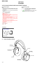
MDR-IF4000
SECTION 2
DISASSEMBLY
Note: Follow the disassembly procedure in the numerical order given.
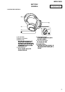
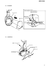
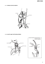
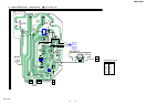
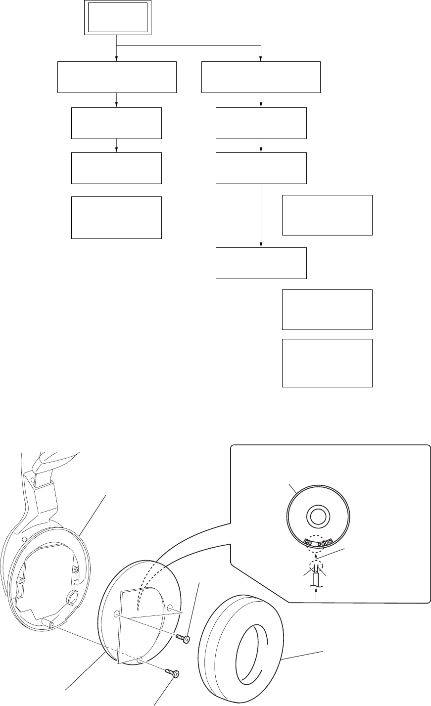
2-2. FRONT PLATE (R) ASSY
• This set can be disassembled in the order shown below.
2-1. DISASSEMBLY FLOW
2-2. FRONT PLATE (R) ASSY
(Page 4)
2-6. FRONT PLATE (L) ASSY
(Page 6)
2-3. RX BOARD
(Page 5)
2-4. HANGER (R)
(Page 5)
2-7. BATT BOARD
(Page 7)
2-8. HANGER (L)
(Page 7)
2-10.HANGER LID (L)
(Page 8)
2-9. WIRING ON THE
LEFT SIDE
(Page 8)
2-11.WIRING ON THE
SW BOARD
(Page 9)
2-12.HOW TO HANG
THE TENSDION
SPRING
(Page 9)
2-5. WIRING ON THE
RIGHT SIDE
(Page 6)
SET
1
ear pad (R)
4
Removal the solder at 2 places.
2
two screws
(P 2.6x6)
3
screw (P 2.6x6)
5
front plate (R) assy
from RX board
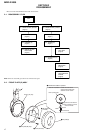
driver (R-CH) side
housing (R) assy
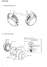
Note for installation : Solder the leads at the
places shown below with
attention to their colors.
Connect a red lead to
the marked one of the
driver terminals.
natural
RED