


12
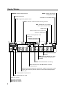
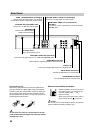
Connections (Continued)
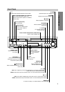
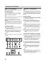
Basic TV Connections
Make one of the following connections, depending on
the capabilities of your TV.
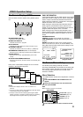
RF coaxial connection
Connect the ANTENNA OUT jack on the DVD/VCR
Receiver to the antenna in jack on the TV using the
75-ohm Coaxial Cable supplied (R).
Note
If you use this connection, tune the TV to the DVD/VCR
Receiver’s RF output channel (CH 3 or 4).
How to set the DVD/VCR Receiver’s RF output
channel
When the DVD/VCR Receiver is turned off,
press and
hold CH/PRESET(+/–) on the front panel for about five
seconds to change the RF output channel (CH 03 or
CH 04). “RF-03” or “RF-04” appears in the display win-
dow.
Audio/Video connection
1
Connect the VIDEO OUT jack on the DVD/VCR
Receiver to the video in jack on the TV using the
supplied video cable (V).
2
Connect the Left and Right AUDIO OUT jacks on
the DVD/VCR Receiver to the audio left/right in
jacks on the TV (A) using the supplied audio
cables.
Note
If you use this connection, set the TV’s source selector
to VIDEO.
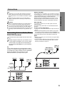
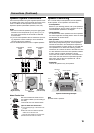
Optional TV Connections
Note
DVD playback can ONLY be done using the S VIDEO
OUT and COMPONENT VIDEO OUT connection options
below.
The tuner and VIDEO will still output through the
ANTENNA OUT (R) or AUDIO/VIDEO OUT (A, V) jack.
(See left)
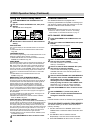
S Video Connection
1
Connect the S VIDEO OUT jack on the DVD/VCR
Receiver to the S Video in jack on the TV using the
supplied S Video cable (S).
2
Connect the Left and Right AUDIO OUT jacks on
the DVD/VCR Receiver to the audio left/right in
jacks on the TV using the supplied audio cables
(A).
Component Video (Color Stream
®
) connection
1
Connect the COMPONENT VIDEO OUT jacks on
the DVD/VCR Receiver to the corresponding in
jacks on the TV using a component video cables
(C).
2
Connect the Left and Right AUDIO OUT jacks of
the DVD/VCR Receiver to the audio left/right in
jacks on the TV (A) using the supplied audio
cables.
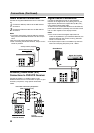
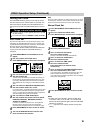
Progressive Scan (ColorStream
®
pro) connection
If your television is a high-definition or “digital ready”
television, you may take advantage of the DVD/VCR
Receiver’s progressive scan output for the highest
video resolution possible.
If your TV does not accept the Progressive Scan for-
mat, the picture will appear scrambled if you try
Progressive Scan on the DVD/VCR Receiver.
1
Connect the COMPONENT VIDEO OUT jacks on
the DVD/VCR Receiver to the corresponding in
jacks on the TV using a component video cables
(C).
2
Connect the Left and Right AUDIO OUT jacks of
the DVD/VCR Receiver to the audio left/right in
jacks on the TV (A) using the supplied audio
cables.
Notes
Set the Progressive Scan to “On” on the DVD setup
menu for progressive signal, see page 21.
Progressive scan does not work with the analog video
connections (yellow VIDEO OUT jack).
ANTENNA
INPUT
R
L
R
Y
Pb
Pr
COMPONENT/PROGRESSIVE
SCAN VIDEO INPUT
AUDIO INPUT
L
VIDEO
INPUT
S VIDEO
INPUT
Rear of TV
Rear of DVD/VCR Receiver
SA V C