


MOON 310LP Phono Preamplifier
Internal Settings (cont’d)
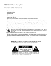
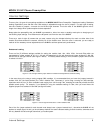
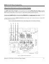
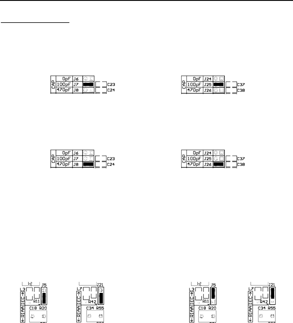
Capacitance Loading:
There are three (3) different settings available for setting the capacitive load; 0pF, 100pF and 470pF which are represented by
jumper sockets J6, J7 and J8 respectively for the left channel and jumper sockets J24, J25 and J26 for the right channel (refer
figure 4 below). The factory default setting is 100pF, therefore jumpers will be found in sockets J7 & J25.
Figure 4: Left and right channel jumper banks for capacitance load adjustments at default settings
Typically, capacitance loading adjustments will only impact the sonic performance of a MM cartridge. We recommend that
when using a MC cartridge, you should set the capacitance load to 0pF by placing the supplied jumpers into sockets J6 and
J24, respectively for the left and right channels. In the event that you’re using a MM cartridge experiment with the three (3)
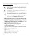
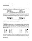
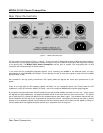
available loads, selecting the load that provides the best possible sound quality. For example, if you decided on using the
capacitance setting of 470pF, then you would insert the supplied jumpers into sockets J8 and J26 (refer to figure 5 below).
Figure 5: Left and right channels set to a 470pF capacitance load
One of the three jumper sockets for each channel must always have a jumper inserted into it, otherwise the 310LP will not
produce an output signal. As well, you should always maintain the same capacitance setting for both channels, otherwise
sound quality may vary between the left and right channels of your audio system.
Equalization Curve:
The MOON 310LP Phono Preamplifier is equipped with circuitry for two (2) different equalization curves; The RIAA standard
and the less common IEC modified curve. The main difference is that the RIAA curve produces a flat frequency response
from 20Hz to 20kHz; The IEC curve acts as a subsonic filter removing inaudible infrasonic bass below 20Hz. Jumper sockets
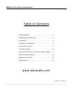
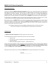
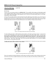
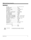
J5 and J21, for the left and right channels respectively, are used to set the 310LP’s equalization curve. These jumpers
sockets have three pins allowing for 2 different possible positions. The factory default position is for the RIAA curve as shown
below in figure 6 where the jumper connects the lower 2 pins. To select the IEC curve, place the jumper over the upper 2 pins
as shown in figure 7 below.
Figure 6: RIAA Equalization curve jumper setting Figure 7: IEC Equalization curve jumper setting
To determine which curve you should use, do as follows: with the 310LP set to the RIAA curve, watch the movement of your
loudspeaker’s bass drivers – if their motion doesn’t follow the pattern of the record currently playing and/or you see excessive
driver movement, chances are you should use the IEC curve to eliminate the subsonic information not present on the record.
____________________________________________________________________________________
Internal Settings 9