MOON 310LP Phono Preamplifier
Internal Settings (cont’d)
Gain Setting:
There are four (4) gain settings available on the MOON 310LP. They are 40dB for MM cartridges and 54dB, 60dB and 66dB
for MC cartridges. However, keep in mind that when using the balanced XLR outputs, each of these gain levels increase by a
factor of 6dB to 46dB, 60dB, 66dB and 72dB respectively (note: to keep the circuit board labelling simple, only the single-
ended RCA gain levels are indicated).
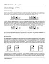
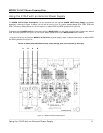
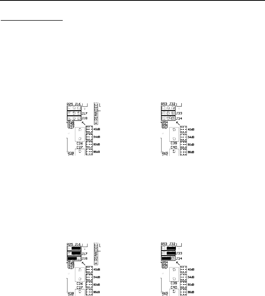
There are three (3) jumpers sockets for each channel that are used to adjust the gain level setting; J16, J17 and J18 for the
left channel; J32, J33 and J34 for the right channel. Each of these jumpers sockets have three pins allowing for 2 different
possible positions. As well, there is a detailed diagram printed on the circuit board, located just below and to the right of each
of these jumper banks, that shows the jumper positioning for the four available gain settings (see figure 8 below).
Figure 8: Left and right channel jumper banks for gain level settings
The factory default gain setting is 40dB, whereby all three jumpers in each bank are mounted to the left. In the event that
you are using a MC cartridge, you will need to change the gain setting to either 54dB, 60dB or 66dB. The basic rule to
determine gain for a MC cartridge is as follows: For a low output MC cartridge (0.7mV and lower), set the gain level to 66dB;
for a medium output MC (0.7mV to 1.5mV) set the gain level to 60dB; for a high output MC (> 1.5mV) set the gain level to
54dB. However, as is the case with the other internal settings, let your ears be best judge as to what the best sounding gain
setting should be. When using a MM cartridge, never set the gain above 40dB, otherwise you will overload the 310LP’s
circuit, resulting in a very distorted output signal.
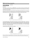
To select a gain level of 60dB, you would mount the jumpers for sockets J16, J17, J32 and J33 to the right, and the jumpers
for sockets J18 and J34 to the left as shown in figure 9 below.
Figure 9: Left and right channels set to a gain level of 60dB
Once you’ve completed all necessary adjustments, carefully place the chassis cover back into place, making sure that the eight
screw holes line up with their respective sockets on the main chassis, and replace the screws using the included allen-key.
____________________________________________________________________________________
Internal Settings 10


