


MOON 310LP Phono Preamplifier
Internal Settings
There are four (4) types of input settings available on the MOON 310LP Phono Preamplifier; Capacitance loading, Resistance
loading, Equalization curve and Gain level. Each setting is adjustable through the use of jumpers. For each type of setting,
there are 2 banks of jumpers – one each for the left and right channels. This is the result of the 310LP’s genuine mirror-
image circuit design which yields exceptional stereo separation.
Always place the preamplifier that your 310LP is connected to, either into mute or stand-by mode prior to changing any of
the following input settings. Then disconnect the AC power cord from the rear of the 310LP.
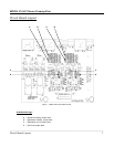
There are a total of eight (8) screws that you must remove using the included allen-key four each on either side of the
chassis. Once these screws are removed, carefully lift off the chassis cover. Once the cover is removed, you are ready to
make all of the necessary internal adjustments to the 310LP to achieve optimal sonic performance.
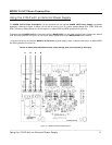
Resistance Loading:
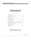
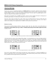
There are five (5) different settings available for setting the resistive load; 10Ω, 100Ω, 470Ω, 1kΩ and 47kΩ which are
represented by jumper sockets J9, J10, J11, J12 and J13 respectively for the left channel and jumper sockets J27, J28, J29,
J30 and J31 for the right channel (refer figure 2 below). The factory default setting is 47kΩ, therefore jumpers will be found
in sockets J13 & J31.
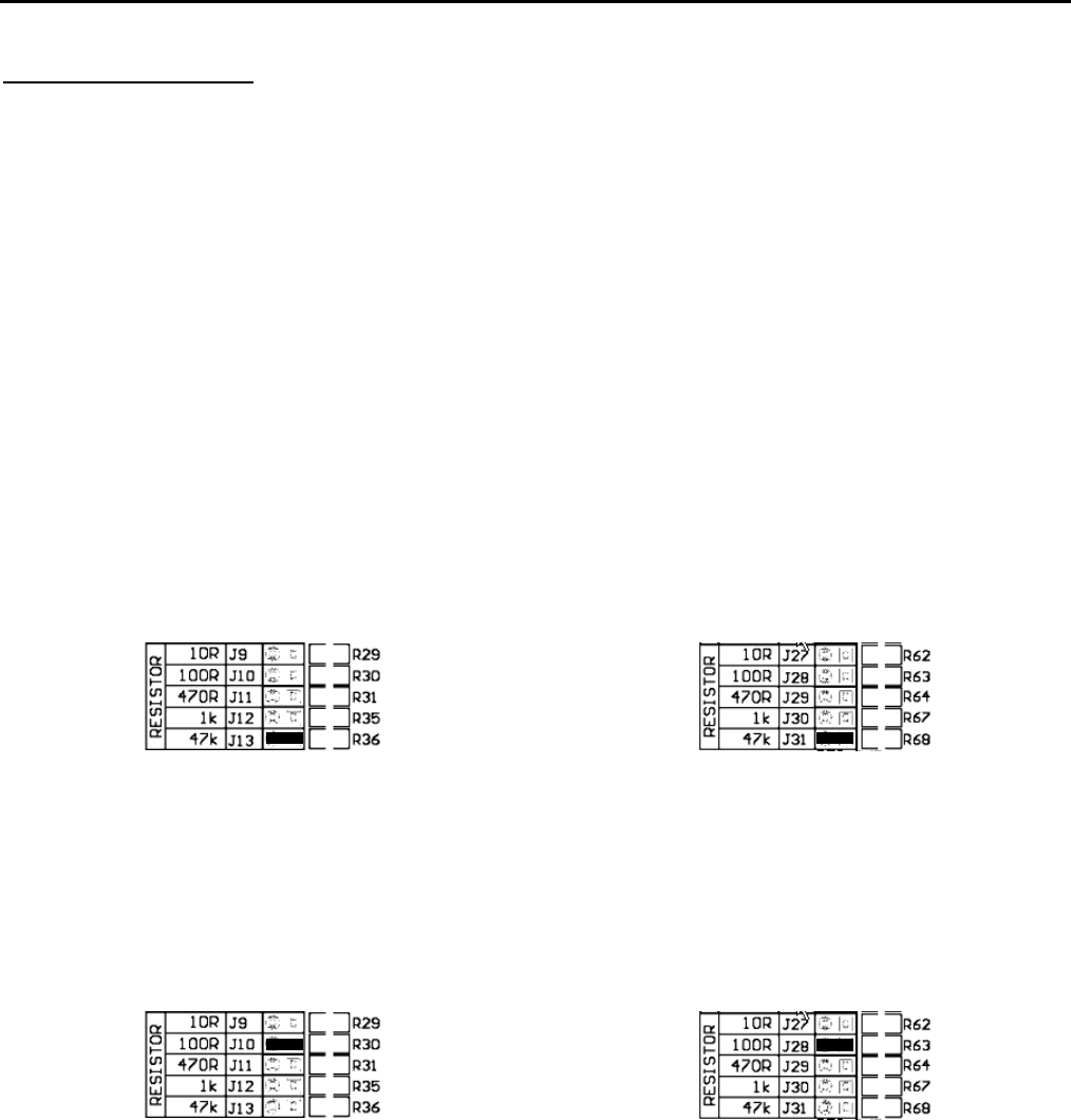
Figure 2: Left and right channel jumper banks for resistance load adjustments at default setting
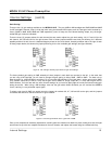
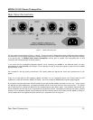
In the event that you’re using a moving magnet (MM) cartridge, it is recommended that you leave the jumpers inserted in
sockets J13 & J31 (the factory default) for a 47kΩ resistive load. Conversely, if you’re using a moving coil (MC) cartridge,
experiment with the four (4) other available loads ranging from 10Ω through 1KΩ, selecting the load that provides the best
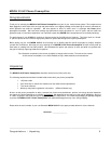
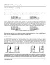
possible sound quality. For example, if you decided on using the resistance setting of 100Ω, then you would insert the
supplied jumpers into sockets J10 and J28 (see figure 3 below).
Figure 3: Left and right channels set to a 100Ω resistance load
One of the five jumper sockets for each channel must always have a jumper inserted into it, otherwise the 310LP will not
produce an output signal. As well, you should always maintain the same resistance setting for both channels, otherwise sound
will vary between the left and right channels of your audio system.
____________________________________________________________________________________
Internal Settings 8