


8
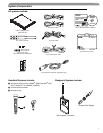
Shure UHF-R Wireless
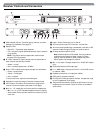
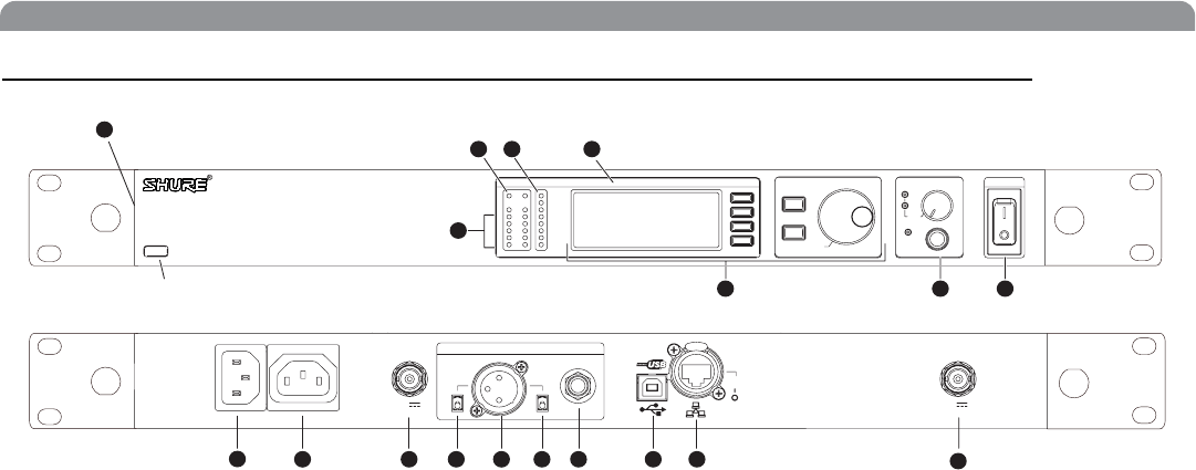
Receiver Controls and Connectors
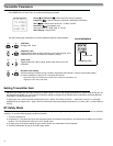
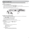
³ SYNC Infrared (IR) port. Transmits group, channel, and other
settings to a transmitter. See page 15.
· Squelch LEDs.
• Blue (On) = Transmitter signal detected
• Off = no signal or signal squelched because of poor reception
or no tonekey
NOTE: The receiver will not output audio unless at least
one blue LED is illuminated.
» RF LEDs. Indicate RF signal strength from the transmitter at
each antenna and diversity condition.
•Amber=normal
• Red = overload (greater than –25 dBm)
¿ Audio LEDs. Indicate audio signal strength from transmitter.
• Green = signal present
• Yellow = normal peak
•Red=overload
To correct this level, adjust the transmitter gain.
´ Indicates the name and range of receiver frequency band.
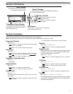
² LCD Interface. Provides a convenient way to program the
receiver from the front panel (see detail on next page).
¶ Monitor. 1/4” output jack and volume knob for headphones.
•
Monitor Clip
LED indicates headphone audio is clipping.
•
Dual models
: Push the knob to switch from receiver one to re-
ceiver two.
º Power switch. Powers the unit on and off.
¾ AC mains power input, IEC connector. 100–240 Vac.
µ AC mains power passthrough (unswitched). Use with an IEC
extension cable to supply AC power to another device.
¸ Diversity antenna inputs A and B.
Note: Antenna inputs are DC biased. Use only antenna
combiners and accessories listed in page 19. Some
types of antenna splitters or other products may short
the DC power and damage the receiver.
¹ Mic/Line switch. Changes output level –30 dB (XLR output
only).
Ƹ Electrically balanced XLR output jack
ƹ Lift/GND switch. Lifts ground from Pin 1 of the XLR connec-
tor (default = GND).
ƺ Impedance balanced 1/4” output jack (200:)
ƻ USB jack for computer interface.
Ƽ RJ-45 jack for Ethernet network interface. Accepts both regu-
lar and “ruggedized” RJ-45 plugs.
ƽ Temperature-activated fan ensures top performance in high
temperature environments. Clean fan screen as needed to
remove dust.
antenna A in
12.7V out
150mA
receiver outputs
lift
GND
line
mic
sync
RF Audio
OL
AB
XX YYY-ZZZ MHz Navigate
ENTER
EXIT
OFF
push
Control
POWER
Monitor
Monitor Clip
push
antenna B in
12.7V out
150mA
networking
ethernet
RJ-45
2
3
4 5
6 7 8
10 11
11
12 13 14 15 16 17
UR4S
Wireless Receiver
with Audio Reference Conpanding
17
ᕡ
18
9
200ȍ
balanced low Z
network
activity