


8ENGLISH
CONTROLS AND CONNECTORS
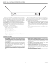
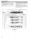
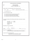
Front Panel
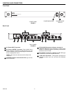
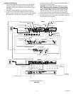
Back Panel
AC Power INPUT Connector.
AC Power OUTPUT Connector. Each UA845 has a
Power OUTPUT connector for daisy-chaining up to five
(5) Shure Model U4 UHF Diversity Single or Dual Receiv-
ers to a single power source.
NOTE: This connector does not work for Shure UC4
Receivers.
ANTENNA IN Ports, Channel A & B. BNC-type connec-
tors for antennas.
RF CASCADE Connectors (Output connector 5),
Channel A & B. BNC-type connectors for adding a fifth
receiver, or additional UA845's, permitting more wireless
receivers to be connected.
RF OUTPUT Connectors, Channel A & B. BNC-type
connectors for up to four wireless receivers.
12 Vdc OUT Connectors. These power connectors are
designed to power up to four (4) Shure UC4 Wireless
systems.
UA845
UHF ANTENNA DISTRIBUTION SYSTEM
FRONT PANEL
FIGURE 1
1 2
POWER INDICATOR POWER ON/OFF
SWITCH
1 2 3 4 5 3 4 5
6 6
BACK PANEL
FIGURE 2
1
2
3
4
5
6