


11 ENGLISH
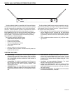
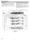
Multiple UA845 Setup
1. Connect the CASCADE ports (connector 5) for RF OUTPUT
Channels A and B of one UA845 to the ANTENNA INPUT,
channels A and B, of a U4 receiver, a UC4 receiver, or a sec-
ond UA845.
2. If desired, connect additional units in the same manner.
3. To daisy-chain U4 Receivers together with Power OUTPUT
cables, connect the Power OUTPUT connector of the UA845 to
the Power INPUT connector of one receiver. Connect the
remaining receivers similarly. Connect the POWER INPUT of
the unit to an AC power supply.
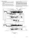
WARNING: When adding additional UA845's to a system,
each UA845 should be connected to a separate power
supply. No more than five (5) receivers can be powered
from a single UA845. Daisy-chaining multiple UA845's
through the Power OUTPUT ports will overload a single
power supply, possibly causing damage to the equipment.
4. To power Shure UC4 receivers, connect the power input ports of
the UC4 receivers to the 12 Vdc OUT of the UA845. Up to four
UC4 Receivers can be powered.
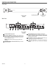
MULTIPLE UA845 SETUP
FIGURE 9
ANT A IN ANT B IN
ANT B IN
ANT A IN
TO POWER SUPPLY
ANT B IN
ANT A IN
ANT A OUTS
12 VDC POWER CONNECTOR
ANT B OUTS
12 VDC POWER CONNECTOR
AC PWR OUTPUT
AC PWR INPUT
CASCADE B
CASCADE A
AC PWR OUTPUT
AC PWR INPUT
12 VDC PWR INPUT
UA845
U4 RECEIVER
U4 RECEIVER
UA845
TO POWER SUPPLY
U4 RECEIVER
TO RECEIVERS
TO
RECEIVERS
TO UA845 ANT B IN
TO UA845
ANT A IN
TO
RECEIVERS
TO
RECEIVERS