7
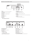
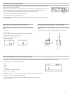
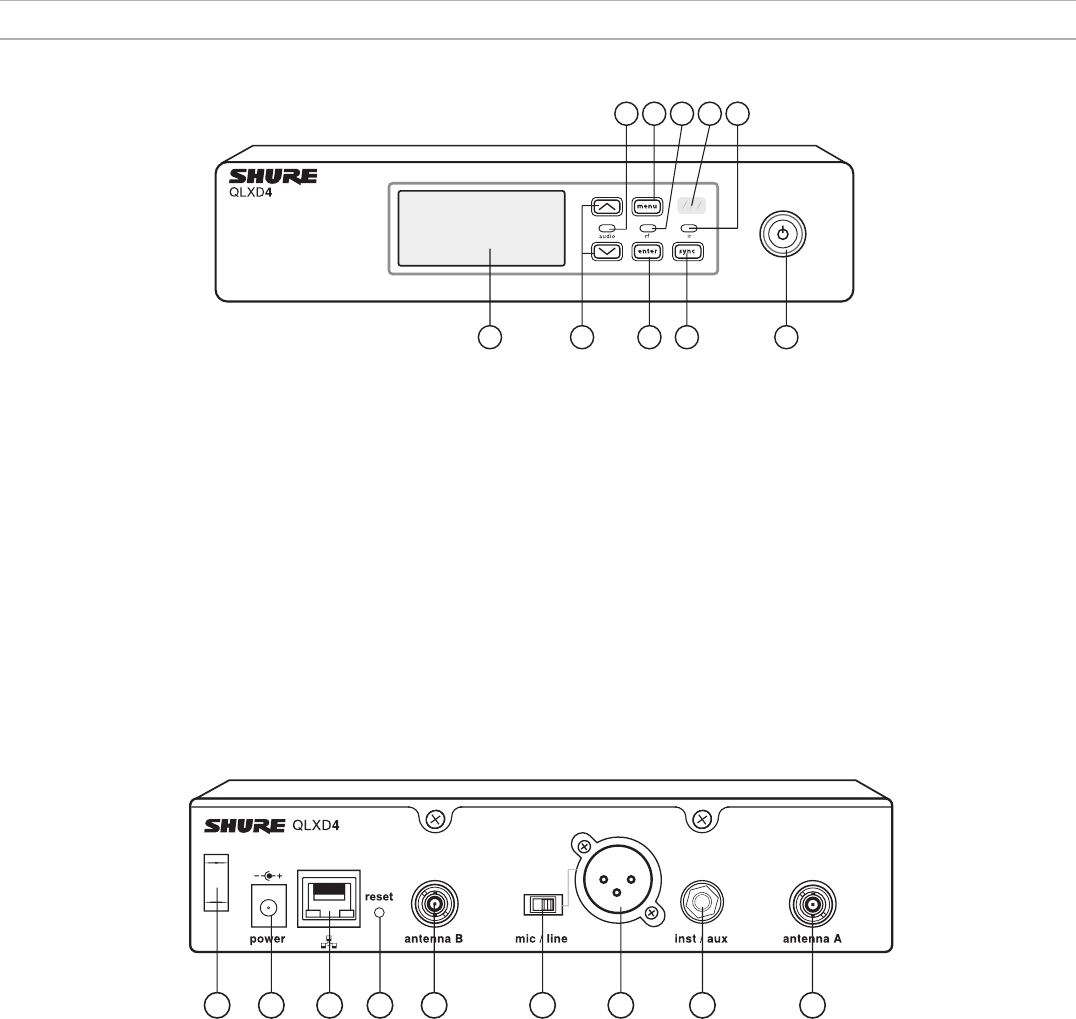
Receiver Front and Back Panels
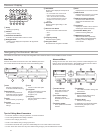
1 2 3 4 5
6 7 8 9
10
① Display
Shows menu options, receiver and transmitter settings.
② Arrow Buttons
Adjust gain setting or change menu parameters.
③ Enter Button
Press to save menu or parameter changes.
④ Sync Button
Press to activate IR sync.
⑤ Power Switch
Powers receiver on or off.
⑥ Audio LED
- Green = normal
- Yellow = signal approaching limiter threshold
- Red = limiter engaged to prevent clipping
⑦ Menu Button
- Press to access or select menu screens
- Press to cancel pending changes
- Press and hold to return to the home screen
⑧ RF LED
Illuminates when RF link with transmitter is active.
⑨ IR Window
Align with the transmitter IR window during an IR sync to automatically program
transmitters.
⑩ Sync LED
- Blinking: IR sync mode is enabled
- On: Receiver and transmitter aligned for IR sync
11 12 13 14 15 16 17 1518
⑪ Power Cord Strain Relief
Secures power cord.
⑫ Power Supply Jack
Connection point for DC power supply.
⑬ Ethernet Port
For network connection.
- Amber LED (network speed):
off = 10 Mbps, on = 100 Mbps
- Green LED (network status):
off = no network link, on = network link active
flashing = rate corresponds to traffic volume
⑭ Receiver Reset
Press to restore receiver default settings.
⑮ Antenna Connectors
BNC connector for receiver antennas
⑯ Mic/Line Switch
Sets output level to microphone or line.
⑰ XLR Audio Output
Balanced (1: ground, 2: audio +, 3: audio - )
⑱ 1/4" Instrument/Auxiliary Output
Impedance Balanced (Tip: audio, Ring: no audio, Sleeve: ground)


