


3
INTERNAL DIP SWITCH FUNCTIONS (FIGURE 5)
All MX392 and MX393 models have internal DIP switches
that allow the user to program the On/Off switch so that it fits
the application. To gain access to the DIP switches, remove
the grille retainer screw, the grille retainer, the foam screen,
and the grille, as shown in Figure 2.
MX392 LOGIC TERMINAL DEFINITIONS (FIGURE 6)
LOGIC GND Terminal: Connects to the logic ground of
an automatic mixer, switcher, or other equipment. Can be
modified to prevent ground loops. Refer to the “MX392 Log-
ic Modifications” paragraph.
SWITCH OUT Terminal: Provides a TTL logic low when
the membrane switch is pressed. This signal is available at
all times for all switch settings. The Switch Out function pro-
vides a momentary closure when S1 is Off and a latching clo-
sure when it is On.
LED IN Terminal: Can be modified to remotely control the
LED by flipping DIP switch S3 in the microphone to the ON
position. As supplied, the LED IN terminal draws 5 Vdc.
When this is shorted to the LOGIC GROUND terminal, the
LED turns on.
MX392 LOGIC MODIFICATIONS
To gain access to the logic terminals, remove the grille re-
tainer screw, the grille retainer, foam screen, and grille, as
shown in Figure 2.
Isolating Logic Ground from Audio Ground
1. Remove jumper R40 from the top of the circuit board.
2. Make sure LOGIC GND terminal connects to the logic
ground of the automatic mixer, switcher, or other equip-
ment.
Changing SWITCH OUT Terminal to Always Momentary
To accommodate interface equipment requiring momen-
tary closure of the microphone (even when the desired mi-
crophone function is latching on/off), proceed as follows:
1. Remove R45 from the top of the circuit board.
2. Reinstall R45 at location R46 on the top of the circuit
board.
Custom Switch Modifications
S4 is available for custom logic modifications. When S4 is
in the ON position, pad W4 is connected to pad W5.
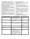
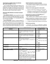
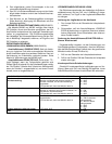
DESIRED MICROPHONE FUNCTION USER ACTION REQUIRED DIP SWITCH SETTINGS
Push to Mute (As Shipped) Press and hold switch to temporarily mute micro-
phone; release switch to unmute
LED turns on when microphone is active
S1 = OFF
S2 = OFF
S3 = OFF
S4 = OFF
Push to Talk Press and hold switch to activate microphone;
release switch to mute
LED turns on when microphone is active
S1 = OFF
S2 = ON
S3 = OFF
S4 = OFF
Push On/Push Off Press switch to toggle microphone on or off
LED turns on when microphone is active
S1 = ON,
S2 = ON for muted initial state
S2 = OFF for active initial state
S3 = OFF
S4 = OFF
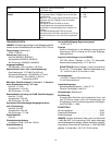
Switch Deactivated, Microphone Always
Active
LED Always OFF S3 = ON
S4 = OFF
Switch Deactivated, Microphone Always
Active
Short LED IN terminal to LOGIC GROUND termi-
nal
LED Always ON
S3 = ON
S4 = OFF
Automatic Mixer Mode (MX392 models
only)
If S1=OFF, SWITCH OUT signal will be momen-
tarily logic low when switch is pressed
If S1=ON, SWITCH OUT signal will be latching
logic low when switch is pressed
Connect SWITCH OUT signal to various logic in-
puts of automatic mixer for custom functions
Connect mixer channel GATE OUT to microphone
LED IN. LED on microphone turns on when its
channel is gated on
S1 = ON or OFF
S3 = ON
S4 = OFF
NOTE: S4 is available for custom applications.