


2
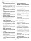
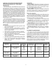
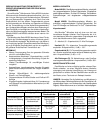
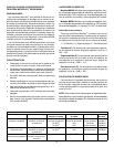
SECURING MICROPHONES TO A MOUNTING SURFACE
(FIGURE 1)
1. Remove the Phillips screw from the bottom of the micro-
phone base, then remove the retainer.
2. Remove the grille and foam screen by carefully inserting
a pointed tool into the edge of the grille and prying it open.
3. Place the microphone in the desired location and, using
a pencil, trace the location of the screw holes through
the microphone. Then drill a starter hole for each sup-
plied screw.
4. Cover the rear two foam pads on the microphone with
tape so that it slides more easily across the mounting
surface.
5. Install the two supplied screws in the desired location on
the mounting surface.
6. Reinstall the grille, foam screen, and retainer, and se-
cure them with the Phillips screw.
7. Using a knife or a razor blade, cut a slot into each of the
two foam pads covering the slots below the screw holes
on the bottom of the microphone.
8. Position the microphone so that the screw holes fit over
the screw heads. Then slide the microphone so that the
screw heads are in the slots in the microphone base.
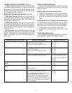
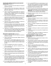
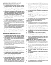
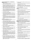
PAINTING THE MICROPHONE (FIGURE 2)
1. Remove the Phillips screw from the bottom of the micro-
phone base, then remove the retainer.
2. Lift off the retainer, grille, and foam screen. Then sepa-
rate the foam screen from the grille.
3. If using an MX393 model, disconnect the Tini Q-G
con-
nector. If you are using an MX392 model, disconnect the
wire leads from the screw terminals, untie the knot in the
cable, and slide the cable out.
4. Remove the rubber strain relief.
5. Place the supplied plastic paint shield over the exposed
circuit board.
6. Place the supplied adhesive masking strip over the
switch panel on the front of the base.
7. Cover the connector opening on the microphone base
with the supplied round rubber plug.
8. Cleanse the surfaces to be painted with denatured alco-
hol or naphtha.
9. Carefully spray paint the microphone base and grille the
desired color. To avoid filling grille holes, apply paint in
a thin layer. Allow paint to dry thoroughly before reinstal-
ling the grille and foam screen.
10. If using an MX392 model, thread the cable through the
base, then through the rubber strain relief.
11. If using an MX392 model, tie a single overhand knot in
the cable as near to the end of the cable jacket as pos-
sible. Then insert the rubber strain relief back into the
cable exit hole.
12. Reconnect the wire leads to the screw terminals.
13. Use fine sandpaper to remove any paint that may have
adhered to the bottom edges of the grille.
IMPORTANT: For proper shielding, maintain electrical
continuity between the grille and the metal base.
14. Reinstall the retainer, grille, foam screen, and Phillips
screw.
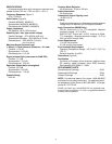
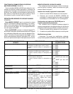
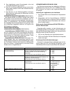
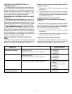
CHANGING THE MICROPHONE CARTRIDGE (FIGURE 3)
1. Remove the Phillips screw from the bottom of the micro-
phone base, then remove the retainer.
2. Remove the grille and foam screen by carefully inserting
a pointed tool into the edge of the grille and prying it open.
3. Remove the Phillips screw from the cartridge retaining
bracket, then remove the bracket.
4. Use your fingers to unscrew the cartridge from the mi-
crophone assembly.
5. Use your fingers to screw the replacement cartridge into
place.
6. Reinstall the cartridge retaining bracket and secure it
with the Phillips screw.
7. Reinstall the grille, foam screen, and retainer, then se-
cure them with the Phillips screw.
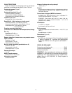
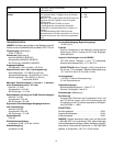
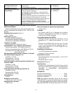
RE–ROUTING CABLE FOR BOTTOM EXIT
(FIGURE 4, MX392 MODELS ONLY)
1. Remove the Phillips screw from the bottom of the micro-
phone base, then remove the retainer.
2. Carefully lift off the grille and foam screen, using a
pointed tool or screwdriver.
3. Disconnect the wire leads from the screw terminals on
the microphone printed circuit board.
4. Untie the knot in the cable, and slide the cable out.
5. Remove the rubber strain relief from the inside of the mi-
crophone.
6. Insert the cable through the slot between the two screw
holes, starting from the bottom of the microphone base.
7. Tie a single overhand knot in the cable from inside the
microphone. This will help prevent the cable from being
accidentally pulled out.
8. Connect the wire leads to the screw terminals on the mi-
crophone circuit board.
9. Insert the supplied round rubber plug in the unused
cable exit hole.
10. Reinstall the grille, foam screen, and retainer, and se-
cure them with the Phillips screw.
11. Secure the microphone to the mounting surface. Refer
to the “Securing Microphones to a Mounting Surface”
paragraph.