


4
ENGLISH
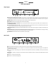
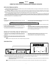
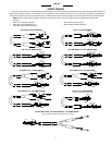
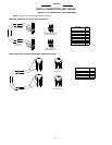
DFR11EQ PANELS
FRONT PANEL
ᕡ BYPASS DFR FILTERS Button and LED. Press this button to suspend feedback reducer operation and remove feedback filters from
the audio path. The bypass does not affect the equalizer, delay or limiter. When the LED illuminates, the feedback reducer is bypassed.
ᕢ SIGNAL LED. Illuminates when input signal is present. Intensity varies with input signal level.
ᕣ CLIP LED. Illuminates when the input signal is within 6 dB of clipping.
ᕤ SCENE Selection Buttons and LEDs. Press one of these three buttons to select a pre-set scene. When a scene is selected, the cor-
responding LED will light.
ᕥ LOCK/CLEAR Filters Button and LED. Press and release this button to lock the filters you have set. Hold down the button for three
seconds, and the filters will clear. The LED indicates that the filters are locked.
ᕦ DFR FILTER LEDs (10). Indicate when individual feedback filters are active. When a filter changes or is added, the LED flashes, then
stays on.
ᕧ DATA LED. Flashes in unison with the feedback filter LEDs when the detector is deploying a new feedback filter or changing an existing
one, and also blinks whenever the unit is communicating with a connected computer.
ᕨ POWER LED. LED illuminates when unit is attached to a power supply.
BACK PANEL
ᕡ Power Connector with Integral Fuse. Connects to AC power. The fuse is located in the drawer below the connector.
ᕢ 9-Pin RS-232 Port. Connects the unit to a computer. For use with DFR11EQ software and for DSP firmware upgrades. (Compatible with
AMX and Crestron systems.
ᕣ Shure Link Interface. Allows linking of up to 16 Shure Link devices (DFR11EQs, DP11EQs, and UA888s), which may be accessed by
computer.
ᕤ DIP Switches. Switches 1 through 4 are used to select the device ID. Switches 5 through 10 change other available options. See DIP
Switches.
ᕥ Separate ¼” and XLR audio output jacks.
ᕦ Combined ¼” and XLR audio output jacks.
ᕢᕣ
ᕡ
ᕤᕥ
ᕦ
ᕧᕨ
ᕢᕣᕡ
ᕤ
ᕥ
ᕦ