navigate
navigate control monitor
power
clip
push
1
2
push
enter
exit
audioRF
audioRF
sync
AXT400
A 470-698 MHz
Dual Wireless Receiver
A B
OL
A B
OL
New Freq
Scan
Options
Squelch
G:01 Ch:01
470.350 MHz TV: 14
Band: G1
: AXT600
Frequency
Server
7
Interference Detection
Dual Digital Signal Processors (DSP) in the receiver analyze the RF signal for signs of interference that can degrade the audio signal. When interference is present, the re-
ceiver screen turns red and displays one of the following warning messages:
Interference Alert
Displayed on the home screen when low-level interference is detected. Interference at this level may not be audible or may only cause a slight disruption to the audio signal.
All receiver controls can still be accessed, and If the interference is not audible, a frequency change may not be necessary.
If Interference Avoidance is set to Auto mode, a frequency change will not occur unless the strength of the interference increases to trigger an Interference Detected
message.
Interference Detected
Displayed when high-level interference likely to disrupt the audio signal is detected. The menu screen displays on-screen options for changing to a clear frequency or if
Interference Avoidance mode is set to Auto, the channel will automatically switch to a clear frequency deployed by the Spectrum Manager.
If the Interference clears without being addressed or if a frequency change is made by the Spectrum Manager, the LCD screen will return to its normal color. The detection
message indicating time elapsed since the interference occurred will remain on the screen for up to 60 minutes or until dismissed.
On-Screen Frequency Change Options
When Avoidance mode is set to Prompt, the following on-screen options are available when interference is detected:
• Switch: Deploys a clear backup frequency from the Spectrum Manager when selected
• Manual: Accesses the frequency menu to make a frequency change using the control wheel
• Ignore: Suppresses the interference warning message
Detection Sensitivity
The sensitivity setting allow you to vary the timing of warning messages to match the RF conditions and the need to avoid interference.
Normal
• Generates a message in response to low levels
of interference well below the audibility threshold
• Provides more time to react to messages
• Interference Detection is suppressed when
received signal strength is below the Exclusion
threshold
More Sensitive
• Generates a message in response to moderate
levels of interference below the audibility
threshold
• Provides more time to react to messages
• Interference Detection can trigger at low received
signal levels, regardless of the Exclusion
threshold setting
Less Sensitive
• Detects interference at a level just below the
audibility threshold
• Fewer detection messages
• Less time to react to messages
• Interference Detection is suppressed when
received signal strength is below the Exclusion
threshold
Setting up an Audio Channel
Setting the Frequency Band
Set to the Receiver to the same frequency band as the
transmitter.
1. From the home menu screen, select Radio.
2. Press the control wheel to highlight Band.
3. Turn the control wheel to set the receiver band to
match the transmitter band.
4. Press the ENTER button to save.
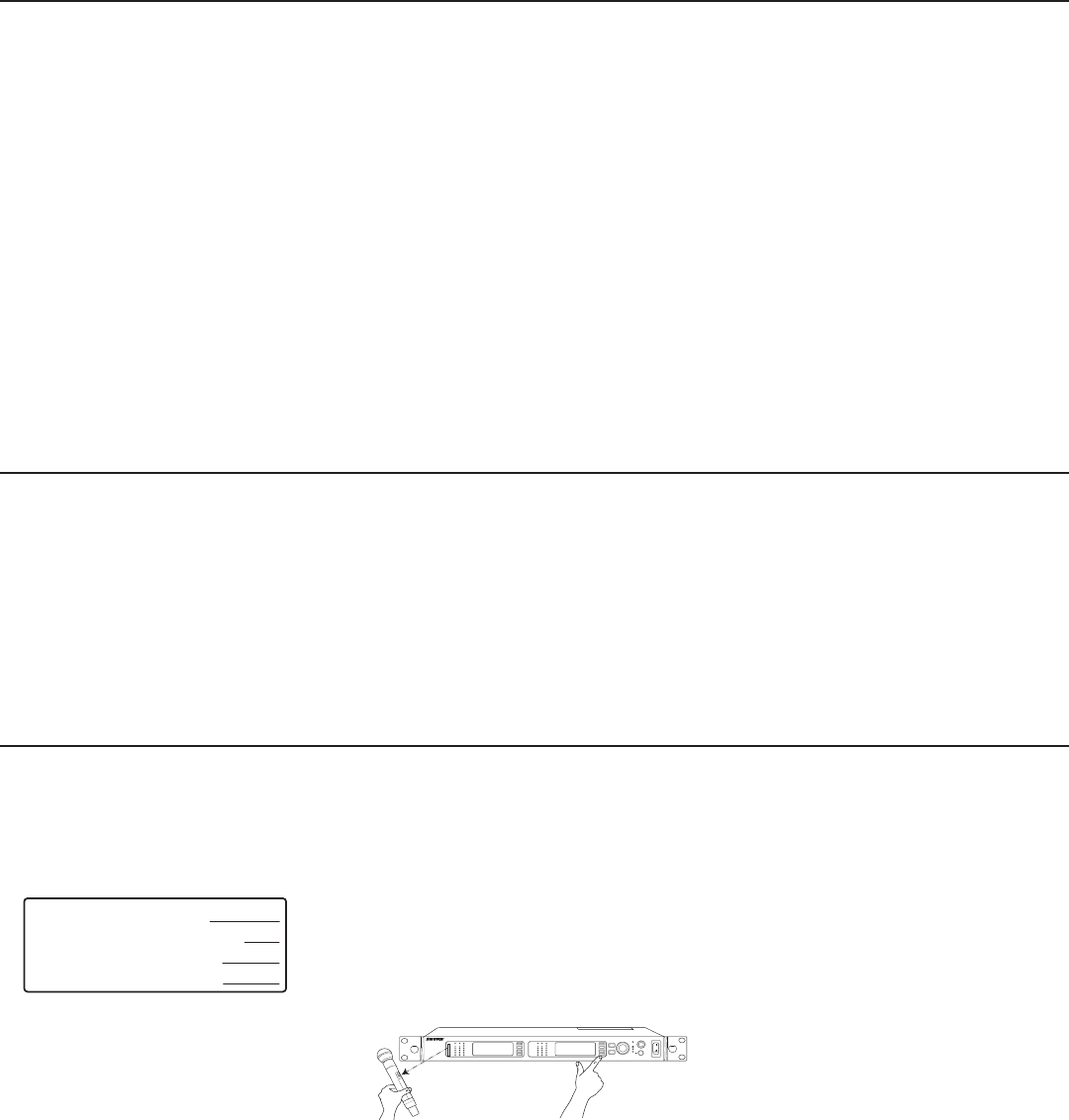
Linking a Transmitter using IR Sync
The IR Sync function forms a link between a transmitter
and the receiver and automatically sets the transmitter
frequency.
1. Menu: Tx
2. Align the transmitter with the IR port on the front
panel. The red IR sync LED on the receiver IR port
will illluminate to indicate correct alignment. Press
Sync.
3. The display indicates if the IR sync is successful.
Check transmitter alignment and select Retry if a
failure occurs. The receiver passes an audio signal
if successful.
4. Linking a transmitter creates a persistent control re-
lationship with the receiver channel, enabling remote
control and synchronized frequency changes when
ShowLink is active.
• Up to 2 transmitters can be linked, which
allows alternate transmitters to be added to the
channel and remotely controlled.
• Turn the control wheel to select the transmitter
in slot 1 or slot 2 before pressing Sync.
5. When a transmitter is successfully linked, a confir-
mation is displayed and the link status icon appears
to the left of the channel name on the receiver home
menu. Link status is not maintained with UHF-R
series transmitters.
6. Transmitters can be unlinked from the channel,
clearing the link relationship.
• From the home screen menu, select Tx
• Turn the control wheel to select the device ID of
the transmitter to be unlinked
• Press the Unlink menu option or link another
transmitter to overwrite the selected link slot


