


navigate
navigate control monitor
power
clip
push
1
2
push
enter
exit
audioRF
audioRF
sync
1
2
7
8
12
14
9
10
11
3
4
5 6
13
2
5 6
3
4
AXT400
A 470-698 MHz
Dual Wireless Receiver
A B
OL
A B
OL
antenna
in
cascade
out
12.7V OUT
150 mA
B A
AXT400
2
3
6
18
4
5
16
17
1
7
8
9
10
11 13
12 14 12 14
11 13
15
Input 100-240 V ~ 50/60 Hz 0.8A max.
(5.8A max. outlet loaded)
Output 100-240~
5A max. 50/60 Hz UNSW.
analog outputs receiver 2
line
mic
lift
GND
AES3 output
in
word
clock
thru
Term 75Ω
analog outputs receiver 1
line
mic
lift
GND
Class 1 PoE
4
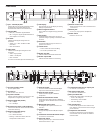
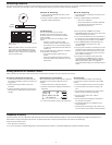
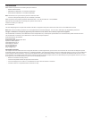
Front Panel
① Sync - Infrared (IR) Port
Infrared (IR) port. For sending parameter presets
(IR Preset) to a transmitter and linking the
transmitter and receiver to the same channel.
② Squelch LEDs
• Blue (On) = transmitter signal detected
• Off = no signal or signal squelched because of
poor reception or no tonekey
③ RF LEDs
Indicates the RF signal strength from the
transmitter.
• Amber (1-5) = -90 to -70 dBm in 5 dBm
increments
• Red = RF overload
④ Audio LEDs
Indicates the audio signal strength from the
transmitter.
• Green = signal present
• Yellow = normal peak
• Red = overload
To correct an overload, adjust the transmitter gain.
⑤ LCD display
Each channel has an LCD display for viewing
settings and parameters.
⑥ Menu navigation buttons
Use to select and navigate through parameter
menus.
⑦ Enter button
The Enter button flashes when an action or
parameter change is pending. Press Enter to save
the value.
⑧ Exit button
Cancels parameter changes or returns to a
previous menu screen.
⑨ Control wheel
• Push to select menu items for editing
• Turn to edit a parameter value
⑩ Monitor clip LED
Indicates audio overload when illuminated.
⑪ Monitor output LED
Indicates channel selection for monitoring.
⑫ Monitor volume knob
Adjusts monitor volume. Push to monitor channel
1 or channel 2.
⑬ Monitor jack
6.5 mm (1/4”) output jack for headphones.
⑭ Power switch
Power the unit on or off.
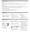
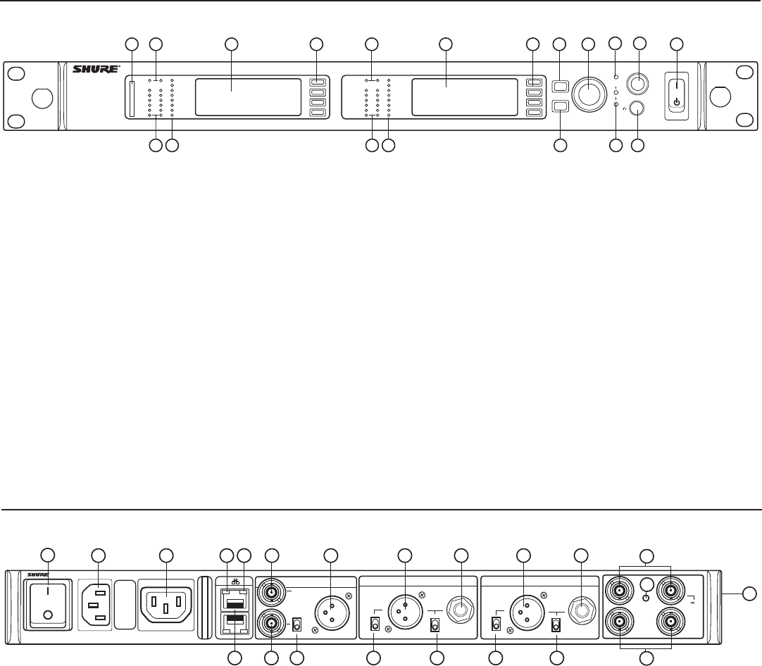
Rear Panel
① AC power primary switch
AC main power switch.
② AC power in
IEC connector 100 - 240 V AC.
③ AC power cascade
Use IEC extension cables to connect up to 5 rack
components to a single AC power source.
④ Network speed LED (amber)
• Off = 10 Mbps
• On = 100 Mbps
⑤ Ethernet ports: Class 1 PoE enabled (2)
Connect to an Ethernet network to enable remote
control and monitoring.
⑥ Network status LED (green)
• Off = no network link
• On = network link active
• Flashing = network link active, flash rate
corresponds to traffic volume
⑦ Word clock input
Connect to resolve the AXT400 AES3 digital
output to an external word clock source.
⑧ Word clock thru output
Passes word clock signal to additional
components.
⑨ Word clock termination switch
Set to thru when passing signal to additional
components. Set to 75Ω when thru connection is
not used.
⑩ AES3 digital audio output
24-bit digital audio output for channel 1 and
channel 2.
⑪ Line/Mic switch
Changes the output level 30 dB (XLR outputs
only).
⑫ Transformer balanced XLR audio output
For channel 1 and channel 2.
⑬ Ground lift switch
Lifts the ground from pin 1 of the XLR connector
and the sleeve of the ¼” jack.
⑭ Transformer balanced 1/4" output jack
For channel 1 and channel 2.
⑮ RF antenna input jacks
For antenna A and antenna B.
⑯ RF input status LED
Indicates the voltage status of the RF input.
• Green = DC voltage on
• Red flashing = fault condition
• Off = DC voltage off
⑰ RF cascade ports
Passes the RF signal from one receiver to the
next, allowing up to 5 receivers to share a single
pair of antennas.
⑱ Temperature activated fan
Ensures top performance in high temperature
environments. Clean fan screen as needed to
maintain airflow.