


ON
OFF
DHCP
Shure
AXT620
Edit ID
Flash
Mute
[Device ID]
Gain: +10
Power: 10mW Lock: OFF
RF Output: On
6
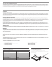
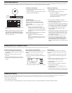
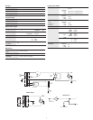
Networking Receivers
The receiver uses an Ethernet connection to network with other components. For automatic network configuration, use a DHCP enabled Ethernet switch such as the Shure
AXT620 or an Ethernet router with DHCP service. Use multiple Ethernet switches to extend the network for larger installations.
Multiple device network example using the Shure AXT620
Ethernet switch
Automatic IP Addressing
1. If using a Shure AXT620 Ethernet switch, set the
DHCP switch to ON.
2. Set the IP mode to automatic for all devices (Util >
Network > Mode > Automatic)
Manual IP Addressing
1. Connect the Spectrum Manager and receivers to an
Ethernet switch.
2. Set the IP Mode to Manual for all devices:
• Menu: Util > Network
• Use the control wheel to set valid IP addresses
for all devices. Set the subnet mask for all
devices to the same value.
Troubleshooting
Use only one DHCP server per network
All devices must share the same subnet mask
All devices must have the same level of firmware
revision installed
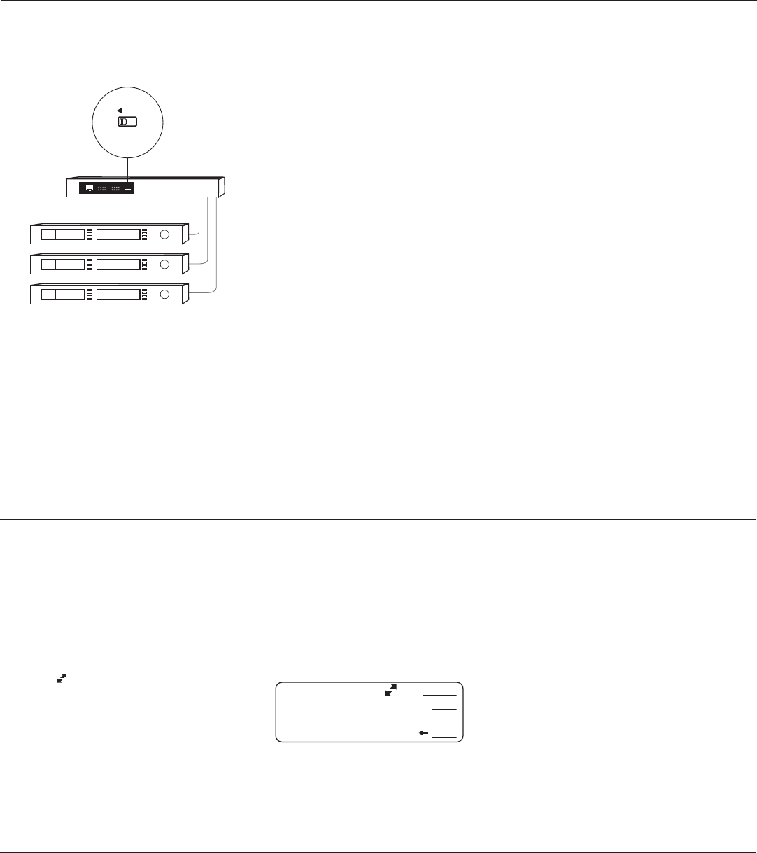
Look for the network icons on the display of each
device:
• If the icon is not there, check the cable
connection and the LEDs on the network jack.
• If the LEDs are not on and the cable is plugged
in, replace the cable and recheck the LEDs and
network icon.
Use the Find All utility (Util > Network > Find All)
to view devices on the network:
• The Find All report lists all devices on the
network.
• Check the IP address for devices not shown in
the Find All report to ensure that they are on the
same subnet.
To check connectivity of WWB6 to the network:
1. Start WWB6 software and use Inventory view to see
devices connected to the network.
2. If not, find the IP address from one of the devices on
the network (such as an AXT400 receiver) and see if
you can ping it from the computer running WWB6.
3. From a WINDOWS/MAC command prompt, type
"ping IPADDRESS" of the device (e.g. "ping
192.168.1.100").
4. If the ping returns success (no packet loss), then the
computer can see the device on the network. If the
ping returns failure (100% packet loss), then check
the IP address of the computer to ensure it’s on the
same subnet as the device.
5. If the pings are successful and the devices still
do not show up in the WWB6 inventory, check to
ensure all firewalls are either disabled or allow the
WWB network traffic to pass to the application.
Check that firewall settings are not blocking network
access.
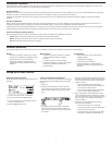
Adding ShowLink for Remote Control
Adding a ShowLink Access Point enables remote control of a linked Axient transmitter from the front panel of the receiver.
Connecting a ShowLink Access Point
1. Connect the Access Point to the Ethernet port of
the receiver to establish a network connection and
supply power.
2. Position the access point within range of the
transmitter.
3. Check the transmitter and receiver menus for the
ShowLink icon, indicating that remote control is
possible.
Remote Control of Transmitters
When a linked transmitter is within range of a ShowLink
Access Point, the transmitter adjustment menu is
enabled.
1. From the home screen, select Tx > Adjust
2. Press the control wheel to highlight a parameter for
adjustment.
3. Turn the control wheel to change a parameter value.
ShowLink Test
To check the ShowLink network and connectivity,
you can use the ShowLink test mode in the AXT400
receiver:
1. Connect the AXT610 Access Point to the network.
2. Link a transmitter to the receiver by doing an IR
sync.
3. You should see the ShowLink icon on the receiver
display next to the transmitter information.
4. From the receiver menu: Util > More >
ShowLink Test.
5. Use the control wheel to highlight a transmitter to
test, and then press Start.
6. The ShowLink test will run and display a signal
strength indication.
7. If the ShowLink signal strength is low, check the an-
tenna connection on the AXT610 and the transmitter.
Note: For smaller systems, connect the receivers
to one another using the Ethernet ports on the
back panel. The devices fall back to compatible
addresses if the IP mode is set to automatic and
there is no DHCP server.
Frequency Diversity
Frequency Diversity uses two independent radio frequencies sent from an AXT200 handheld transmitter or from two AXT100 bodypack transmitters connected with a "Y"
cable to deliver a single uninterrupted audio channel. To optimize performance, Frequency Diversity mode must match the transmitter type.
To set Frequency Diversity mode:
1. Menu: Options > Diversity
2. Turn the control wheel to select FD-Bodypack for AXT100 bodypack transmitters or to select FD-Handheld for AXT200 handheld transmitters.