


INSTALLATION
SPEAKER POSITIONING
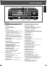
5. VIDEO IN/OUT
– MONITOR OUT – output jack for connecting to the video input
of a TV set. The TV set must then be switched to that input.
– VCR 1 PLAY/REC – PLAY(input) and REC(output) jacks for
connecting the video output and input of a VCR
– LDP PLAY – input jack for connecting the video output of a
LDP.
6. LOW LEVEL PRE-OUT
– SUBWOOFER PRE–OUT – output jacks for driving
SUBWOOFER.
Connect these jacks to SUBWOOFER input jacks of
separate amplifier or a powered SUBWOOFER.
– CENTER PRE–OUT – output jacks for connecting a separate
amplifier to drive the center speaker. Connect these jacks to
input jacks of a separate amplifier for center channel speaker
only.
– REAR PRE–OUT – output jacks for connecting a separate
amplifier to drive the rear speakers. Connect these jacks to
input jacks of a separate amplifier for rear channel speakers
only.
7. FRONT PRE–OUT/MAIN–IN
– FRONT PRE–OUT – When a separate power amplifier is
used to drive the front speakers, connect these jacks to the
power amplifier.
– FRONT MAIN–IN –When a separate pre-amplifier is used for
front channel, connect these jacks to the pre-amplifier.
Note : When you do not use the PRE–OUT or MAIN–IN,
always connect the PRE–OUT and MAIN–IN jacks with
jumper plugs.
8. REAR SPEAKERS
Terminals for connecting a pair of rear speakers, impedance
of 4 Ω each, to obtain a surround sound effect.
Note : Always connect two speakers to these terminals.
9. CENTER SPEAKER
Terminals for connecting a center speaker, impedance of 8Ω.
10
. FRONT SPEAKERS
Terminals for connecting two pairs of speakers, impedance of
8 – 16Ω (L = left, R = right).
One of the wires of a speaker cable is marked with a color
or rib. Connect the marked wire to the red terminal, the non-
marked wire to the black one.
11.
DIGI LINK
III
SYSTEM CONTROL
(colored green) – remote control jacks for connection to the
corresponding DIGI LINK
II
or
III
jacks of a Sherwood CD
(Compact Disc) or tape player. Connect this jack to the DIGI
LINK
III
jack of the external Sherwood equipment that uses
the DIGI LINK
II
or
III
remote control system.
These jacks have been added to maintain compatibility with
other Sherwood products.
12.
MULTI-ROOM IN
Jack for connecting the multi room adaptor. Connect this jack
to the output of the adaptor.
For information on the multi-room adaptor, contact the Xantec
Corporation at 1-800-843-5465.
POWER
13
.AC POWER CORD
Connecting the receiver to the wall socket.
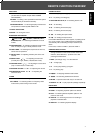
14.
OUTLETS
– Switched output for connecting AC power plugs from various
units such as cassette deck, CD player, etc.
(Maximum total capacity is 1 A or 100 W).
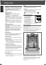
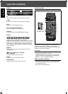
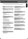
CONNECTING HEADPHONES
Connect a headphone with a 1/4"
plug to the PHONES jack.
– Inserting the plug will not
disconnect the speakers.
– Turn the speakers off by
pressing the SPEAKER switches
once, press again to turn
speakers on. Also ensure receiver is
not in surround modes
– Only in Surround off mode
you can enjoy private listening with a headphone.
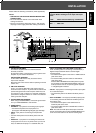
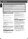
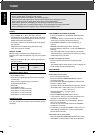
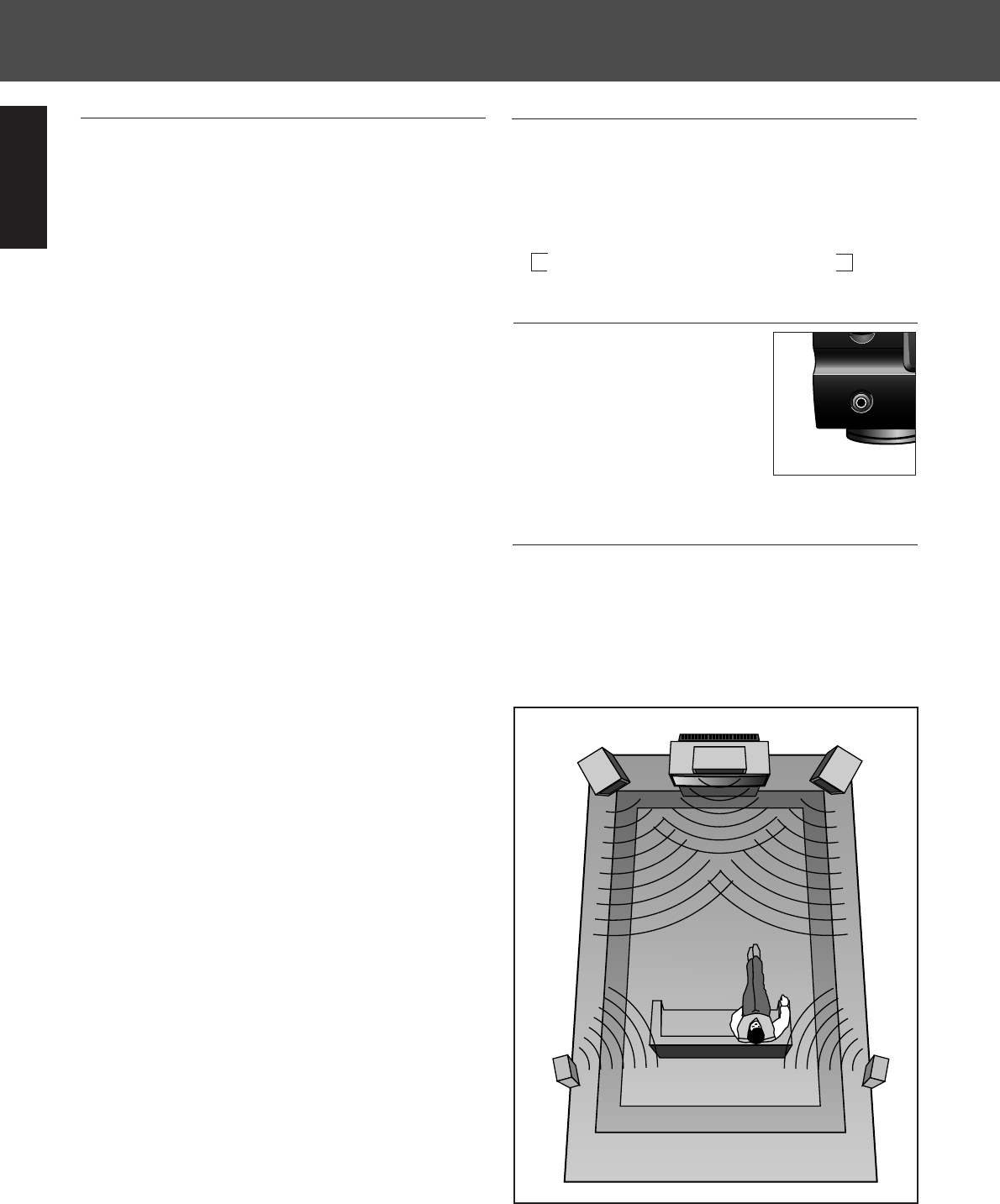
SPEAKER POSITIONING
To obtain the best surround sound effect in your home, place the
speakers as shown below.
The left and right speakers should be placed about 1 m (40")
from the TV set.
The center speaker should be above or below the TV set.
The rear speakers should be placed 2~3 feet above the ear level
of a seated listener on the direct left and right of them.
Refer to the fold-out for additional information.
Note : to avoid interference with the TV picture, use only
magnetically shielded front speaker systems.
After making all necessary connections (some may not apply to
your system set-up), your system is ready for use. In the next
chapter, we will describe how to operate your
R-525 receiver.
4
Standby mode - Switched AC outlet off
Power on mode - Switched AC outlet on
LEFT
TV
RIGHT
CENTER
SPEAKER
SURROUND
LEFT
SURROUND
RIGHT
PHONES
PHONES
ENGLISH