


XL-HF201P
2 – 1
CHAPTER 2. ADJUSTMENTS
[1] CD Section
• Adjustment
Since this CD system incorporates the following
automatic adjustment functions, readjustment is not
needed when replacing the pickup. Therefore,
different PWBs and pickups can be combined freely.
Each time a disc is changed, these adjustments are
performed automatically. Therefore, playback of
each disc can be performed under optimum
conditions.
Items adjusted automatically
1) Offset adjustment (The offset voltage between the
head amplifier output and the VREF reference
voltage is compensated inside the IC)
* Focus offset adjustment
* Tracking offset adjustment
2) Tracking balance adjustment
3) Gain adjustment (The gain is compensated inside
the IC so that the loop gain at the gain crossover
frequency will be 0 dB.)
* Focus gain adjustment
* Tracking gain adjustment
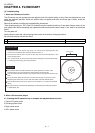
[2] Test Mode
[3] Standard Specification Of Stereo System Error Message Display Contents
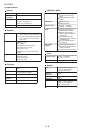
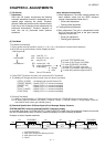
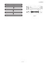
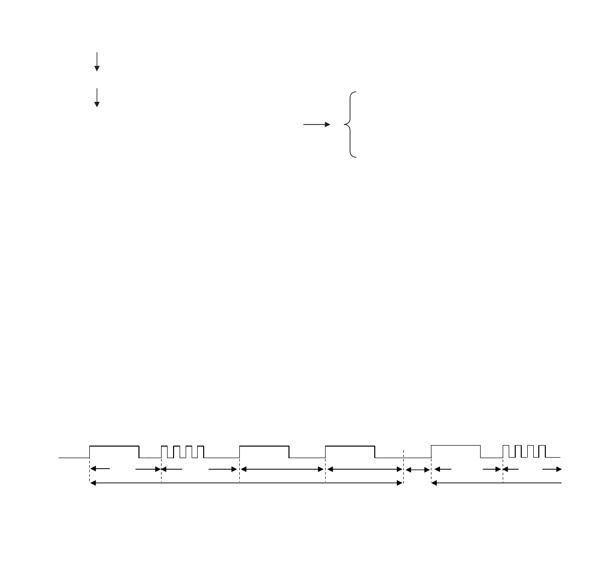
SYSTEM PROTECT detection and AMP PROTECT detection display
In case AMP Shut Down, SYSTEM PROTECT, FAULT PROTECT or AMP Over-Temp Warning Protect has occurred,
the unit will automatically enter to stand-by mode ON/Standby LED willl be flashing as below:-
Example: In case of speaker abnormal
[Test Mode Input Method]
1. During power stand-by condition, press [1] -> [2] -> [4] -> [5] buttons at remote control sequently.
2. MCU will start up with software version display as below.
" H201Hyymmdd "
yyyy : year (Ex, 11)
" H201#zzRR " mm : month (Ex, July -> 07)
dd : day (Ex, 01)
" mmddRxxxx " RR : version (00 ~ 99)
03: after TEST BOARD start
05: after 0ji AUTO start (0.5 ROM)
07: after 0ji DR MTG (1st ROM)
08: after Off Tool (Main Line start)
09: after PP production approval MTG
10: after MP production approval MTG
ZZ : stage development
# : area setting
Rxxxx : Servo F/W version
H : Europe
U : USA
3. Press [EJECT] button at the main unit to enter the KEY Test Mode.
4. The display will change as below for each main unit button is pressed.
[OPEN / CLOSE] : All displays light up with Dimmer Off
[PRESET DOWN] : Display "KEY 1-2" at lower line display
[PRESET UP] : Display "KEY 1-3
" at lower line display
[STOP] : Display "KEY 1-5" at lower line display
[PLAY / PAUSE] : Display "KEY 1-1" at lower line display
[FUNCTION] : Display "KEY 1-2" at lower line display
5. [Existing Test Mode]
5.1. While in Version display or in Test Mode Function press ON / STAND-BY button (remote control / unit).
5.2. All display light up in Dimmer Off (2sec) => Dimmer 1 (2sec) => Dimmer 2 (2sec) => finally display "Clear All"
and execute reset, before goto sta
ndby (demo).
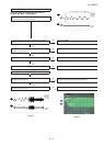
1:SYSTEM PROTECT
2 : AMP Over Temperature Warning Protect
3 : AMP Shut Down Protect
4 : FAULT
OFF
FLASHING
ON
No.1
1 Frame
(Repeat)
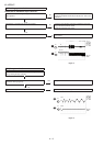
OFF OFF
( 3Sec )
No.2
No.3 No.4
No.1
No.2
( 3Sec )
( 3Sec )
( 3Sec )
OFF
ON
ON
OFF
FLASHING
ON
OFF
( 3Sec ) ( 3Sec )
( 3Sec )