


XL-HF201P
8 – 1
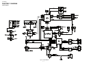
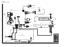
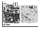
CHAPTER 8. CIRCUIT SCHEMATICS AND PARTS LAYOUT
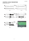
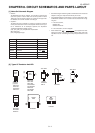
[1] Notes On Schematic Diagram
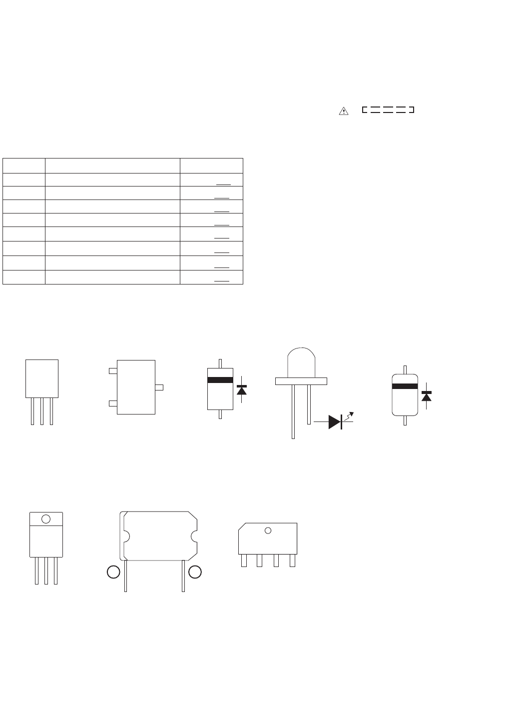
[2] Types Of Transistor And LED
•Resistor:
To differentiate the units of resistors, such symbol as K and M are
used: the symbol K means 1000 ohm and the symbol M means
1000 kohm and the resistor without any symbol is ohm-type resis-
tor. Besides, the one with “Fusible” is a fuse type.
• Capacitor:
To indicate the unit of capacitor, a symbol P is used: this symbol P
means pico-farad and the unit of the capacitor without such a sym-
bol is microfarad. As to electrolytic capacitor, the expression
"capacitance/withstand voltage is used".
(CH), (TH), (RH), (UJ): Temperature compensation
(ML): Mylar type
(P.P.): Polypropylene
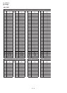
REF. NO
VR700 VOLUME MAX -- MIN
DESCRIPTION POSITION
type
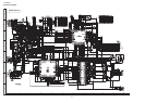
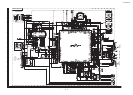
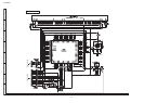
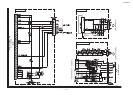
• Schematic diagram and Wiring Side of P.W.Board for this model are
subject to change for improvement without prior notice.
• The indicated voltage in each section is the one measured by Digi-
tal Multimeter between such a section and the chassis with no sig-
nal given.
1. In the tuner section,
indicates AM
indicates FM stereo
2. In the CD section, the CD is stopped.
• Parts marked with “ ( ) are important for main-
taining the safety of the set. Be sure to replace these parts with
specified ones for maintaining the safety and performance of the
set.
SW700 ON/STAND-BY ON -- OFF
SW701 FUNCTION ON -- OFF
SW702 PLAY/PAUSE ON -- OFF
SW703 REWIND ON -- OFF
SW704 FAST FORWARD ON -- OFF
SW705 STOP ON -- OFF
SW706 CD EJECT
ON -- OFF
“
KRA102S
KRC107S
KRC104S
KTA1504GR
KTC3875GR
KRA107S
KTC2875B
KRC102S
B
(3)
E
(1)
C
(2)
TOP
VIEW
TOP VIEW
KTA1274Y
KTC3199
KTC3203Y
KTA1271Y
VIEW
FRONT
ECB
(S)(G)(D)
VIEW
FRONT
VIEW
FRONT
VIEW
FRONT
1
BCE
(1)(2)(3)
1N4004
DRL204F
MA111
TOP VIEW
HSS4148
FRONT
VIEW
304VT2H
TDA8920C
KIA7805A
KIA7809A
KTB772Y
10XB60F
AC AC -+
23