


1
lor much langer. Indeed, lor this reason we also recommend their
use on the 10 mW transmitter (SK 1010-6). IIan accumulator is used
instead 01dry batteries - Le. regular use 01the transmitter leads to
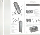
Irequent changing batteries- then the accumulator (e.g.Tr 7/8)
can be easily charged using the automatic charger SZL 1010 (Iig. 6).
Changing the antenna
II any delect occurs, the antenna may be unscrewed through the
slot @ with a small screwdriver.
II the SK
1010is to be used as an hand-held microphone, it is pos-
sible to exchange the long wire antenna by a shorter helical
antenna. This helical antenna is available in the lollowing versions:
A 4 (32-38 MHz)
Antenna
lor SK 1010-6 and SK 1010-7,
Irequency range: 32 - 38 MHz
A 4 (38-45 MHz)
Antenna
lor SK 1010-6 and SK 1010-7,
Irequency range: 38-45 MHz
A 3 (138-260 MHz)
Antenna lor SK1010-9,
Irequency range:138-260 MHz
When ordering please state the exact transmitting Irequency.
Direct your order to your next Sennheiser distributor.
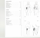
Tips for use
For good high-Irequency radiation It is important to ensure that wire
antenna 0 (Iig. 1) hangs downwards as Ireely as possible. When
using microphones wh ich are to be connected via a cable, the
transmitter and therelore also the antenna should be positioned as
high as possible.
12
13
r
[
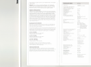
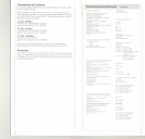
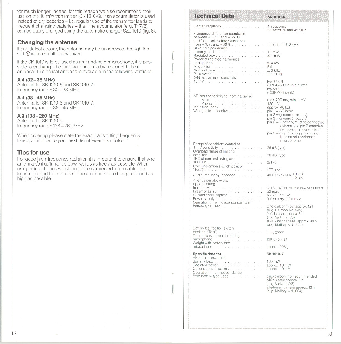
Carrier trequency .
Frequency drift for temperatures
between +10° C and + 55° C
and for supply voltage variafions
trom +10% and -30% .
RF-oufpuf power Info
dummy load. .
Radlated power. . .. .
Powerof radlafed harmonics
and spurios.
Modulaflon. .
Nominal swing
Peakswing. . . . . . .
S/N ratioaf input sensitivity
10 mV .
AF-input sensifivrtyfor nominal sWing
Micro.
Phono.
Inpuf frequency. . .
Wirrng of input socket.
Range ofsenslflvity control at
1 mVsensltivlfy.. .
Overload range af limitlng
ampllfier. . .
THD at nominal swing and
1000 Hz . ... . . .
Levellndlcatlon (switch position
"Test")
Audla frequency response
Attenuation above the
upper Ilmlfing
frequency . .
Preemphasls .
Current consumption
Powersupply. .......
Operation time Independance from
batterytype used .
Batterytest tacility (switch
position "Test")
Dimensions Inmm, Including
mlcrophone. ...
Welght wlth battery and
mlcrophone
Specitic data tor
RF-output power Into
dummy load..
Radlated power.
Current consumptlon
Operation time in dependance
from battery type used
1 frequency
between 30 and 45 MHz
better than:t 2 kHz
10mW
:;;1mW
:;;4nW
FM
:t 8 kHz
:t 10kHz
typ. 72 dB
(DIN45500, curve A, rms)
typ 58 dB
(CCIR468. peak)
max. 200 mV, min. 1 mV
120 mV
approx. 40 kSJ
pin 1= AF-Input
pln 2 ~ ground (-battery)
pln 3 = ground (- battery)
pln 6 ~ +battery,mustbeconnected
externally to pln 7 (enables
remote control operation)
pin 8 = regulated supply voltage
for electret condenser
rnicrophones
26 dB (typ.)
36 dB (typ.)
:;;1%
LED,red.
40 Hzto 12kHz + 1 dB
- 3 dB
> 18 dB/Ocl. (actlve low-pass filter)
50l1sec.
approx. 10 rnA
9 V battery IEC6 F22
zlnc-carbon type: approx. 12h
(e.g. Dairnon No. 249)
NICd-accu: apprax. 8 h
(e.g.VartaTr 7/8)
alkali-manganese: approx. 40 h
(e.g. Mallory MN 1604)
LED,green
150 x 46 x 24
approx. 226 g
SK 1010-7
100 mW
approx. 10 rnW
approx. 40 mA
zlnc-carbon: not recornmended
NiCd-accu: approx. 2 h
(e.g.Varta Tr7/8)
alkali-manganese apprax. 13h
(e.g. Mallory MN1604)