


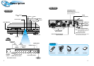
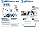
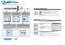
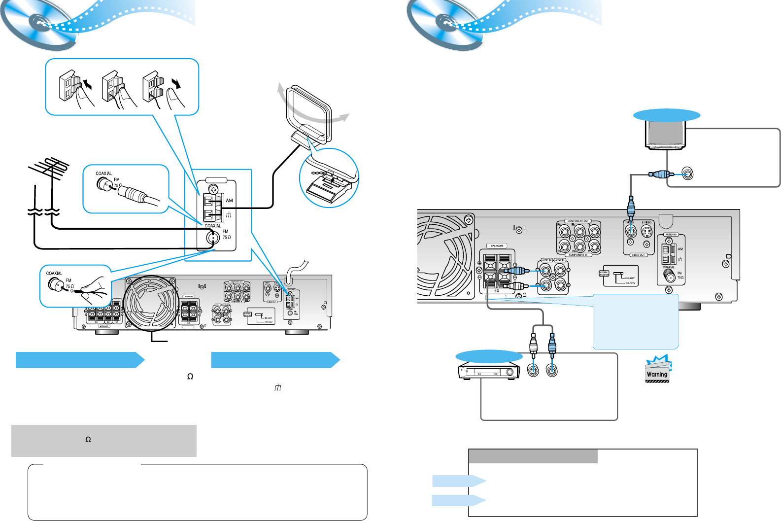
FM antenna connection
1. Connect the FM antenna supplied to the FM 75
COAXIAL terminal as temporary measure.
2. Moderately strain the antenna wire and then
fasten it to a wall or other rigid surface within a
location where reception is good.
•
If reception is poor, connect an outdoor antenna.
Before attaching a 75 coaxial cable (with a standard
type connector), disconnect the supplied FM antenna.
AM(MW) antenna connection
1. Connect the AM loop antenna supplied
to the AM and terminals.
2. If reception is poor, connect an outdoor
single vinyl-covered wire to the AM
terminal. (Keep the AM loop antenna
connected).
12
Connecting the FM and AM
(
MW/LW
)
Antennas
11
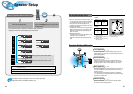
A cooling fan is mounted on the rear panel of the center unit to
prevent abnormal temperature inside the center unit, thus assuring
normal operation of the unit. The cooling fan automatically starts
rotating to supply external cool air to the inside of the center unit
when the internal temperature exceeds the specified limit.
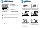
For safety, observe the following carefully.
• Make sure there is good ventilation around the center unit. Poor
ventilation could overheat and damage the canter unit.
• DO NOT block the cooling fan and the ventilation openings or
holes. (If they are blocked by a newspaper or cloth, etc., the heat
may not be able to get out.)
(About the cooling fan)
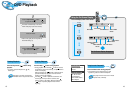
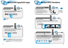
AUX Connections
If FM reception is poor, connect outdoor
FM antenna (not supplied).
AM Loop Antenna (supplied)
Snap the tabs on the loop into the
slots of the base to assemble the
AM loop antenna.
FM Antenna (supplied)
Cooling fan (See “About Cooling Fan” below.)
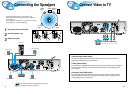
R-REAR-L WOOFER CENTER
R-FRONT-L
IMPEDANCE
123
ANTENNA
R-FRONT-L
IMPEDANCE
VIDEO IN
LR
TV
External Analog
Components
Audio Cable (Red/White)
To view pictures from external
input (AUX 1, AUX 2), first
connect the VIDEO IN jack
(VIDEO 1 or VIDEO 2) and
then connect the VIDEO OUT
jack.
Connect to external equipment with
analog output.
Example: Video, TV, LDP, etc.
•
Always connect the video and
audio connection cables to the
equivalent colored jack.
•
Even if DIGITAL IN is selected, if
the video input jack of an external
analog component is connected to
the player’s VIDEO IN connector,
the player will still output a video
signal from the analog component.
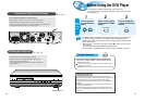
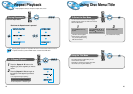
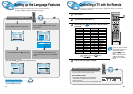
Press the AUX button and select AUX1 IN, AUX2 IN.
Making Analog Input Selection
Press the Function button and select AUX1 IN, AUX2 IN.
Remote Control
Main Unit
If the external analog
component has only one
output jack, you may
connect either L or R.