


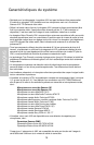
5
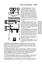
Guided Tour - VM1
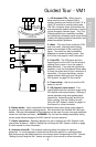
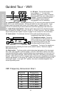
1: A/B Antenna LEDs - When signal is
being received, one of these will be lit
orange, showing you whether the (left) “A” or
(right) “B” antenna is currently being used.
The VM1 constantly scans its two antennas
and automatically selects whichever is receiv-
ing the strongest, clearest signal. This
True
Diversity switching is completely inaudible,
but it effectively increases overall range while
virtually eliminating potential interference and
phase cancellation problems.
2: Meter - This set of three multicolor LEDs
acts as a meter, indicating either battery
power or the strength of the incoming RF
signal. This meter can also be disabled
altogether to conserve battery power. See
#14 on the next page for more information.
3: Peak LED - This LED lights red when
output signal from the VM1 is at the onset of
clipping (that is, when it is on the verge of
being distorted). If you see this light during
operation, move the microphone further away
or lower the output level of your instrument or
transmitter. For more information, see the
section entitled “Setting Up and Using the
VM1 System” on page 8 in this manual.
4: Power switch - Use this to turn the VM1
power on and off.
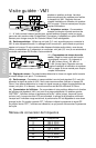
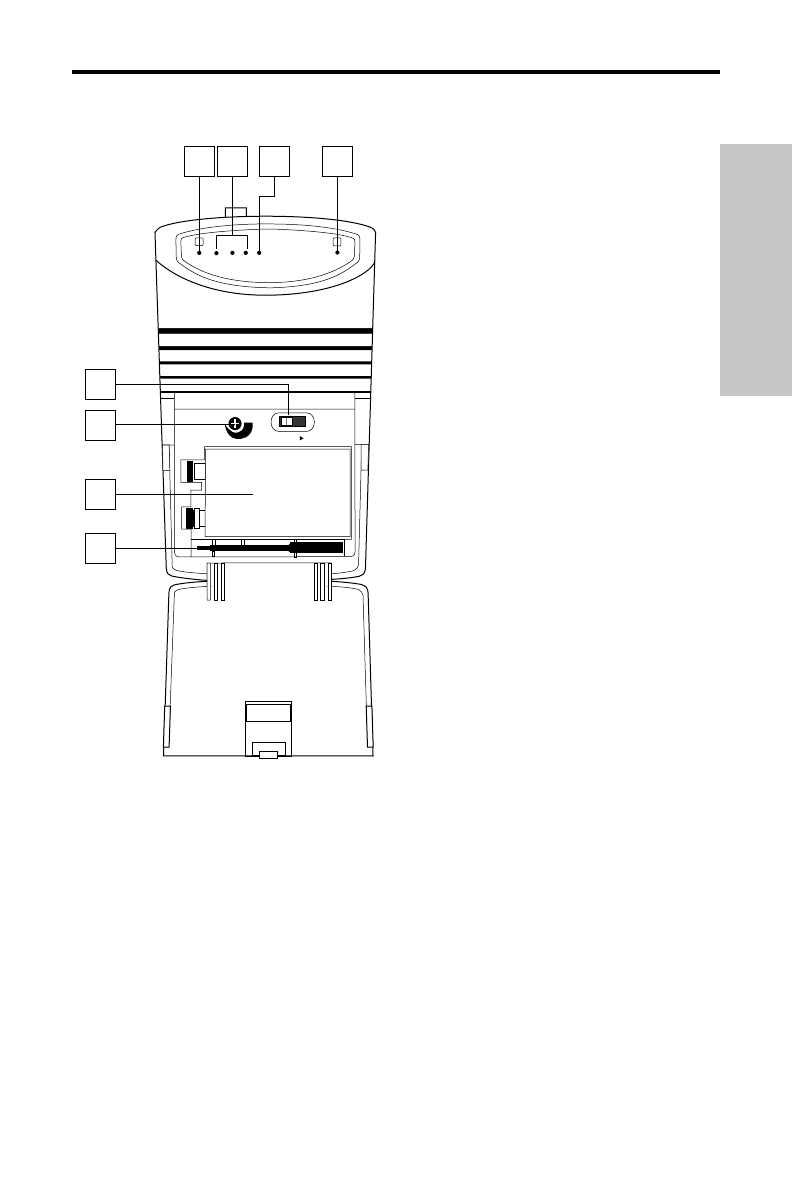
5: SQ (Squelch) Level control - This
control determines the maximum range of the
VM1 before audio signal dropout. Although it
can be adjusted using the supplied plastic
screwdriver, it should normally be left at its
factory setting. See the “Setting Up and
Using the VM1 System” section on page 8 in
this manual for more information.
6: Battery holder - Insert a standard 9-volt alkaline battery here, being sure to observe
the plus and minus polarity markings shown. We recommend the Duracell MN 1604 type
battery. Although rechargeable Ni-Cad batteries can be used, they do not supply adequate
current for more than two hours. WARNING: Do not insert the battery backwards; doing
so can cause severe damage to the VM1 and will void your warranty.
7: Plastic screwdriver - Specially designed for use in adjusting the VM1 Squelch Level
control (see #4 above). See the “Setting Up and Using the VM1 System” section on page
8 in this manual for more information.
8: Antennas (A and B) - The antenna mountings allow full rotation for optimum
placement. In normal operation, both antennas should be placed in a vertical position.
Both antennas can be folded inward for convenience when transporting the VM1. See the
“Setting Up and Using the VM1” section on page 8 in this manual for more information.
ENGLISH
SAMSON
SAMSON
MAX
MIN
POWER
ON
SQ LEVEL
VHF MICRO DIVERSITY RECEIVER
B
A
LOW MID HIGH PEAK
2 3 1
5
7
4
6
1
+
-
VM1