


5
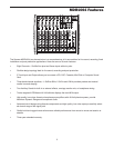
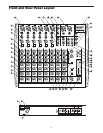
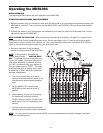
Front and Rear Panel Controls
FRONT PANEL
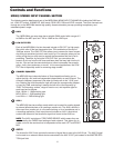
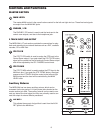
1 MIC IN – Input connector for Low-Noise Microphone pre-
amp.
2 LINE IN–Input connector for Line level inputs.
3 INSERT – 1/-4-inch TRS (TIP/RING/SLEEVE) connector
providing send and recieve channel patch point for out-
board effects.
4 GAIN – Used to set the input level of the mic pre and line
input.
5 LOW CUT – Bass roll off switch at 75Hz used to eliminate
unwanted low end rumble and hum.
`6` HIGH FREQUENCY – Controls the high band of the
Channel Equalizer, +/- 15 dB at 12KHz.
7 MID FREQUENCY – Controls the mid band of the Channel
Equalizer, +/- 15 dB at 2.5KHz.
8 LOW FREQUENCY – Controls the low band of the Channel
Equalizer, +/- 15 dB at 80Hz.
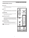
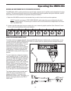
9 AUX 1 – Pre-fader auxiliary send that can be used with
an external effects processor, or to create a cue or moni-
tor mix.
10 AUX 2 – Post-fader auxiliary send that can be used with
an external effects processor, or to create a cue or moni-
tor mix.
11 PAN – Controls the channel’s position between left and
right in the stereo bus.
12 PEAK – Red LED will illuminate indicating when the
GAIN has been adjusted too high.
13 LEVEL – Audio taper fader provides smooth control over
level changes.
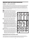
14 RIGHT LINE – 1/4-inch phone input connector for the right
line input for the stereo channels.
15 LEFT LINE - 1/4-inch phone input connector for the Left
Line input for the stereo channels.
16 CONTROL ROOM OUTPUT– Left and Right Control Room
output connectors for connecting a monitor system.
17 MAIN MIX OUTPUT (1/4-inch) – Left and Right Main Mix
balanced output 1/4-inch TRS connectors.
18 MAIN MIX OUTPUT (XLR) – Left and Right Main Mix bal-
anced output XLR connectors.
19 PHONES JACK – Connect stereo headphones here.
20 AUX SEND 1 – Line level output from the Auxiliary 1
bus.
21 AUX SEND 2 – Line level output from the Auxiliary 2
bus.
22 AUX RETURN 2 – Left and right input jacks for con-
necting to the outputs of external line level sources
like those from effects processors.
23 AUX RETURN 1 – Left and right input jacks for con-
necting to the outputs of external line level sources
like those from effects processors.
24 2 TRACK OUTPUTS – Connect to the input of a DAT,
Cassette, Mini Disk or Hard Disk Recording system.
25 2 TRACK INPUTS – Connect the output from a DAT,
Cassette, Mini Disk or Hard Disk Recording system.
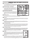
26 POWER LED – Indicates the MDR1064 is powered up.
27 PHANTOM LED – Indicates that the 48 Volt Phantom
Power is on.
28 OUTPUT METER - Twelve segment LED display with
VU ballistics indicates main Mix level.
29 MAIN LEVEL – Used to control the overall volume of
the Left and Right main Mix outputs.
30 PHONES/CR – Adjusts the volume of the control room
speakers or headphones.
31 2 TRACK TO CR – Switches between the main Mix
and the 2 Track in the Control Room output.
32 2 TRACK TO MIX - Switch used to mix the 2 track
input with the mix from the channel inputs.
33 TO AUX 1 - Switch used to route aux return 2 into the
Aux 1 output so that effects can be heard in the mon-
itor mix.
34 AUX RETURN 2 – Used to mix in level of the effects
return.
35 AUX RETURN 1 – Used to mix in level of the effects
return.
36 BALANCE – Controls the channel’s position between
left and right in the stereo inputs.
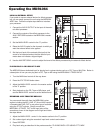
REAR PANEL
A POWER – Switches on the MDR1064’s main power.
B PHANTOM – Engages the 48-Volt Phantom power
supply to microphone pre-amps.
CAC ADAPTOR INLET – Connect External AC power
supply here.