


Operating the MDR1064
13
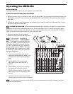
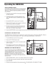
SENDING AN INDEPENDENT MIX TO THE MONITOR SPEAKERS
The MDR1064’s AUX1 auxiliary send can be used to feed a separate set of amplifiers and loudspeakers for stage
monitors. This lets you build one mono mix for the amplifiers and monitor speakers facing the musicians, and the
other stereo mix for the amplifiers and speakers facing the audience.
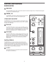
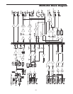
1. Raise the AUX1/MON controls for the channels that you wish to hear from the monitor speakers.
NOTE:
The AUX1 controls are "PRE-FADER SENDS" which means they are not affected by the level
settings of each channel. This allows you to create a mix for the monitors that is independent of the main
LEFT and RIGHT MIX.
2. In order to get the most gain from your monitor mix, use an external graphic equalizer (like a Samson S curve
131) to cut out any frequencies that cause feedback.
010010010010010010010010
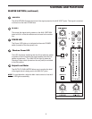
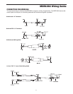
USING THE CHANNEL INSERT JACKS
To further control your signal, channels 1-6 on the MDR1064 feature an insertion point, or “effects loop”, on one
1/4-inch phone jack, INSERT SEND and RETURN. An insertion point is a patch-point that interrupts the signal,
allowing you to bring that signal outside to
be processed by another device. You can
use these connections to interface an
external signal processor like an equalizer,
compressor, noise gate, reverb and other
audio devices. A common application for
the MDR1064’s insert point is using a com-
pressor.
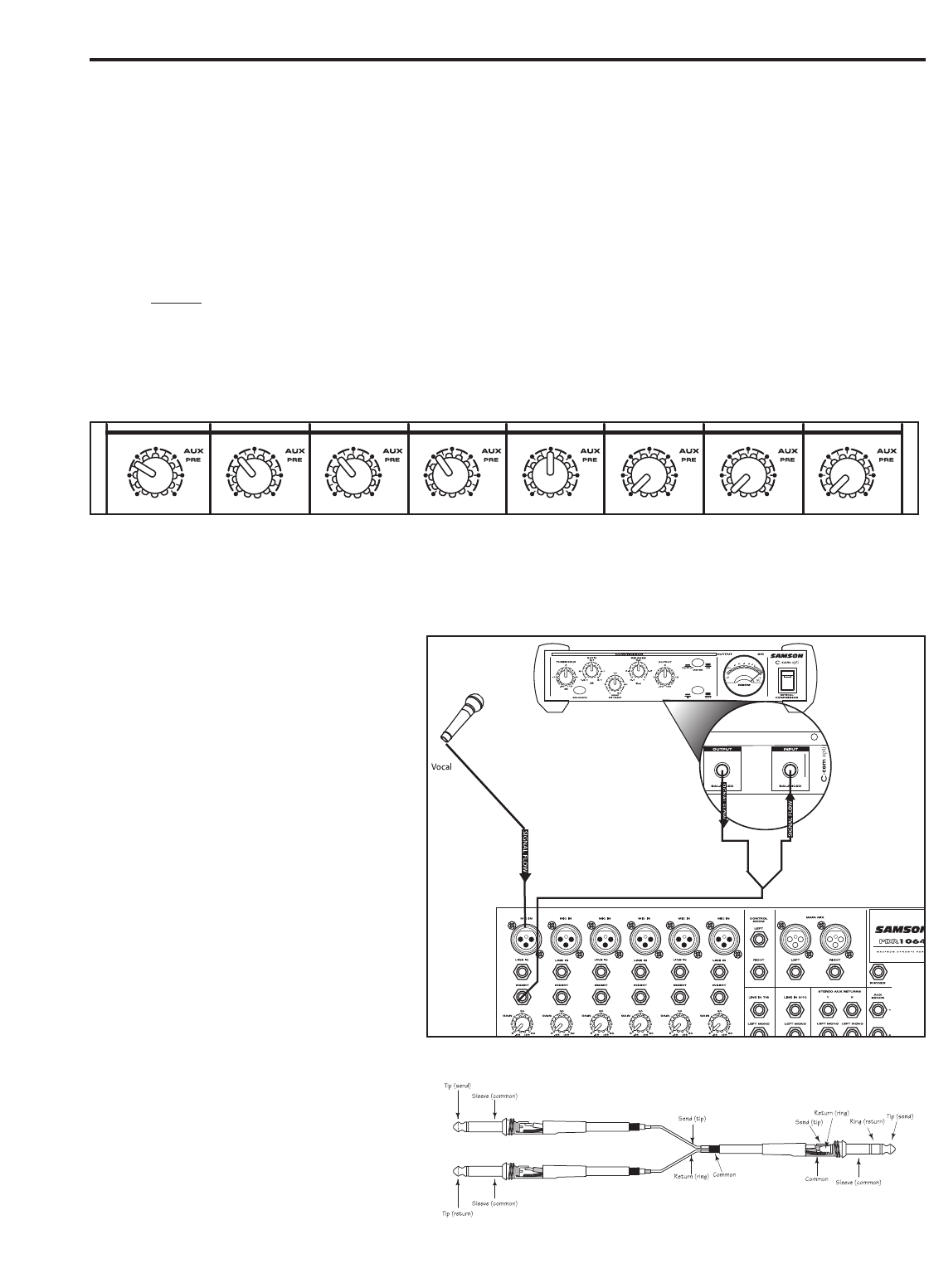
To send a signal to an external processor,
use a standard 1/4-inch “Y” insert cable to
connect the MDR1064 channel insert point.
Connect the TRS (TIP / RING / SLEEVE)
plug to the channel INSERT point, and
then, connect the 1/4-inch (TIP / SLEEVE),
INSERT SEND plug to the input of the
external processor. The signal is sent back
to the MDR1064, using the 1/4-inch (TIP /
SLEEVE), INSERT RETURN plug connect-
ing to the output of the external processor.
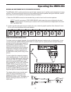
The diagram below shows a typical appli-
cation for using a compressor (in this
example a Samson C com opti) in the
MDR1064’s insertion point. Also below, is a
diagram showing the wire for the TRS ‘Y”
Insert cable.